36 SUPERMAX OWNER’S MANUAL
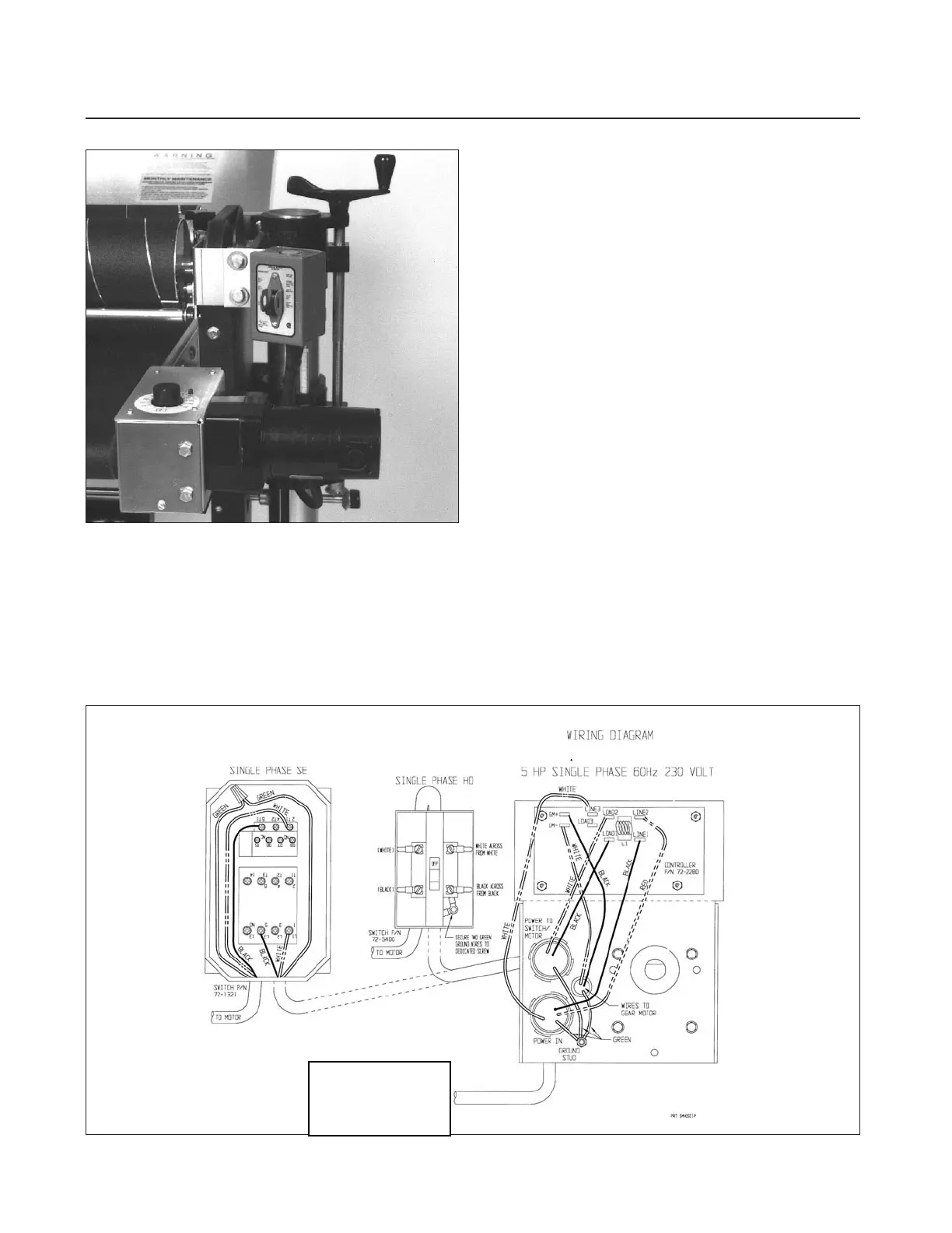
Fig. 45. Conveyor control box and on/off switch,
SUPERMAX HD.
REPLACING ELECTRICAL COMPONENTS
To replace either the variable-speed Intellisand
control, the on-off switch, or the conveyor motor,
use the following disassembly procedure (Fig. 45
and 45A):
First disconnect the power supply to the
machine. Next, remove the bottom plate from the
control box. Loosen the set screw in the shaft cou-
pler, and then remove the four 5/16" bolts that
hold the conveyor motor assembly in place (Fig.
45). Next, remove the assembly from the machine,
then turn it upside down to disconnect the leads
from the components to be removed.
To replace the Intellisand control: remove the
knob by loosening screw and remove nut that was
under knob. Turn housing over, and remove the
nuts holding control board in place. Lift control
board from housing. Install the new controller,
referring to the correct electrical diagram and
reverse the disassembly procedure.
To replace the on-off switch: remove the two
screws holding cover in place. Pull switch from box.
Disconnect wire leads from switch and remove cover
plate from switch. Referring to the correct electrical
diagram, reverse the disassembly procedure.
To replace the gear motor: disconnect the three
wire leads from the controller. Disconnect the
plastic grommet protecting the wires passing
through the sheetmetal. Then remove the four set
screws that hold the motor to the sheetmetal
bracket. Remove the old motor and install the new
motor. Referring to the correct electrical diagram,
reverse the disassembly procedure.
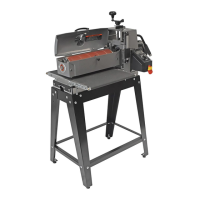
Single phase wiring diagram.
SUPERMAX INTELLISAND
Lovato