TAKE-UP
SCREW NUT
HEIGHT
ADJ.
DRUM
TABLE
HEX NUT &
SET SCREW
GEAR
SETTING UP YOUR SUPERMAX 9
Fig. 10. Adjusting conveyor belt tracking.
result in bent rollers, premature wearing of the
bronze bushings or belt.
Belt Tracking. Belt tracking adjustments are made
while the conveyor belt is running. After the proper
belt tension is obtained (see above), turn the convey-
or unit on and set it at the fastest speed setting.
Watch for a tendency of the conveyor belt to drift to
one side of the conveyor. To adjust the belt tracking,
tighten the take-up screw nut (see Fig. 10) on the
side the belt is drifting toward, and loosen the take-
up screw nut on the opposite side. Adjusting the
take-up screw nuts on either side of the conveyor
allows belt tracking adjustments to be made without
affecting belt tension. NOTE: Adjust the take-up
screw nuts only 1/4 turn at a time. Then allow time
for the belt to react to the adjustments before pro-
ceeding further. Try to avoid over-adjustments.
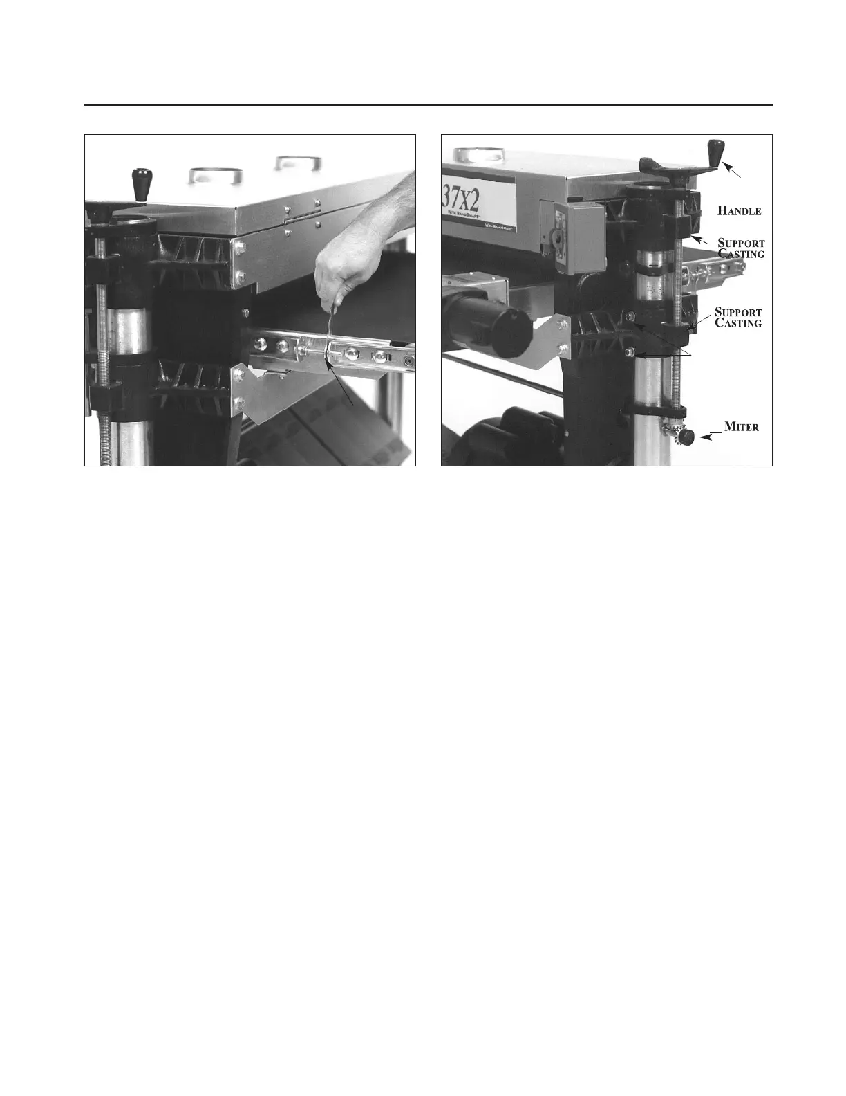
Make sure wrench is below surface when sanding.
C
HECKING
T
ABLE
H
EIGHT
C
ONTROLS
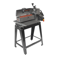
The table height and depth of cut is controlled by
the height adjustment handle (see Fig. 11). Turning
the handle raises or lowers both sides of the table
simultaneously by transferring the handle rotation
through the miter gear and cross bar assembly.
Important: Before using the height adjustment,
be sure to loosen both the set screws located on the
front of both table support castings (see Fig. 3 and
Fig. 11) to allow the table support to slide on both
column tubes. These set screws are tightened for
shipping and must be loosened and readjusted to
Fig. 11. Table height adjustment mechanism.
allow the table support castings to move freely on
the column support tubes. Readjust the set screws
just so they eliminate free-play between the table
support casting and the column tube. To properly
adjust, tighten the set screws (see Fig. 3) only finger-
tight so they lightly touch the column tubes. Then
hold each set screw in position with an Allen
wrench and tighten the hex nut.
Check the operation of the height adjustment
mechanism. If it does not operate smoothly or eas-
ily, further adjustments may be necessary. Refer to
the servicing section of this manual, which begins
on page 24, for further adjustment procedures.
MONTHLY MAINTENANCE
For best results, perform the following recommend-
ed maintenance procedures on a monthly basis:
•
Lubricate conveyor bushings and check for wear.
•
Lubricate all moving parts, such as threaded rods,
washers, and column tubes.
•
Clean sawdust from the sandpaper and the con-
veyor belt.
•
Blow dust from the inside of sanding drum(s) and
the motors.
•
Check all set screws for tightness on parts such as
table support castings, bearings, conveyor coupler,
castings, pulleys, and miter gears.