11
Chapter 1: Introduction
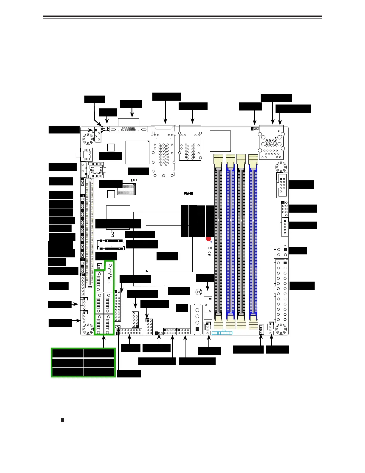
1.4 Motherboard Layout
shown. See the table on the following page for descriptions. For detailed descriptions, pinout
Figure 1-3. Motherboard Layout
JF1
JPI2C1
COM1
I-SATA0
JGPIO1
JSMB1
JPTG1
JBR1
JI2C1
JI2C2
JPG1
JPL1
JPME1
JPME2
JPUSB1
JWD1
DESIGNED IN USA
SRW2
SRW1
JUIDB1
J21
I-SGPIO2
I-SGPIO1
JL1
JOH1
JD1
PJ1
JSTBY1
JPW1
LED8
C
LED7
A
C
LED3
A
C
LEDM1
A
C
BT1
FAN4
FAN3
FAN2
FAN1
VGA
JTPM1
JSD1
I-SATA1
I-SATA4
I-SATA2
I-SATA3
I-SATA5
DIMMB2
DIMMA2
DIMMB1
DIMMA1
JIPMB1
JNVI2C1
X10SDV-F
REV: 2.00
LAN3/4
LAN1/2
PCI-E 3.0 X16
PWR
ON
RST
NIC2
OH
FF
X
NIC1
PWR
LED
HDD
LED
JF1:
USB 2/3
USB 0/1(3.0)
USB 4/5
SLOT7
JBT1
IPMI_LAN
J6
Intel
D-1500
BMC
AST2400
i350
FAN1
FAN2
FAN3
USB0/1
JL1
LAN1/2
LAN3/4
VGA
COM1
IPMI LAN
UID
LED7
JPME2
I-SGPIO2
I-SGPIO1
LED8
JPL1
JBR1
JI
2
C1
JI
2
C2
JOH1
JPG1
JPME1
JSTBY1
LEDM1
I-SATA2
I-SATA1 I-SATA0
I-SATA5
JSD1
JTPM1
JBT1
I-SATA3
I-SATA4
JD1
JWD1
USB4/5
BT1
USB2/3
JF1
JGPIO1
J6
JPUSB1
LED3
JPW1
PJ1
SRW1
SRW2
JIPMB1
PCI-E Slot7
JNVI2C1
CPU
DIMMA1
DIMMA2
DIMMB1
DIMMB2
JPTG1
JSMB1
M.2 Slot
JPI
2
C1
FAN4
Notes:
• " " indicates the location of Pin 1.
• Jumpers/LED indicators not indicated are used for testing only.