12
SuperServer E200-8D User's Manual
Jumper Description Default Setting
JBR1 BIOS Recovery Pins 1-2 (Normal)
JBT1 CMOS Clear Open: Normal, Short: Clear CMOS
JI
2
C1/JI
2
C2 SMB to PCI-Exp. Slots Pins 2-3 (Disabled)
JPG1 VGA Enable Pins 1-2 (Enabled)
JPL1 LAN1/LAN2 Enable Pins 1-2 (Enabled)
JPME1 ME Recovery Pins 1-2 (Normal)
JPME2 Manufacturing Mode Pins 1-2 (Normal)
JPTG1 10Gb Ethernet Enable Pins 1-2 (Enabled)
JPUSB1 USB Wakeup Pins 1-2 (Enabled) (For USB0/1 Only)
JWD1 Watch Dog Enable Pins 1-2 (Reset)
LED Description Color/State Status
LEDM1 BMC Heartbeat LED Green: Blinking BMC: Normal
LED3 Power LED Green: On System Power On
LED7 UID Switch LED Blue: On
LED8 Overheat/PWR Fail/
Fan Fail LED
Red: Solid or Blinking Solid On: Overheat,
Blinking: PWR Fail or Fan Fail
Connector Description
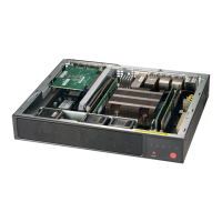
BT1 Onboard Battery
COM1 COM1 Header
FAN1 - FAN4 CPU/System Cooling Fans (FAN4 is on PCB 2.00 only)
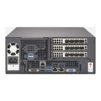
IPMI LAN Dedicated IPMI LAN Port
I-SATA0 - I-SATA5 Intel® Serial ATA Ports (I-SATA0 supports SuperDOM)
I-SGPIO1, I-SGPIO2 Serial Link General Purpose I/O Headers
JGPIO1 General Purpose I/O Expander Header
J6 4-pin Power Connector for power from the motherboard to onboard HDD devices
J21 M.2 Socket (Shared with I-SATA0 when a SATA device is installed in M.2)
JD1 Speaker (Pins 1-3: Power LED, Pins 4-7: Speaker)
JF1 Front Panel Control Header
JIPMB1 4-pin External SMbus I
2
C Header (for an IPMI Card)
JL1 Chassis Intrusion Header
JNVI
2
C1 NVMe I
2
C Header
JOH1 Overheat LED Header
JPI
2
C1 Power Supply SMBus I
2
C Header (On PCB 2.00 only)
JPW1 24-pin ATX Main Power Connector
JSD1 SATA DOM (Device On Module) Power Connector
JSMB1 SMBus Header
JSTBY1 Standby Power Header
JTPM1 Trusted Platform Module (TPM)/Port 80 Connector
JUIDB1