Chapter 2: Installation
2-15
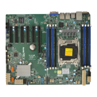
X10SRG-F
REV:1.01
DESIGNED IN USA
BIOS
LICENSE
MAC CODE
IPMI CODE
BAR CODE
4
1
JVRM2
JVRM1
BMC
i350
JUIDB1
FAND
FAN4
FAN3
FAN2
FAN1
FANC
FANA
FANB
JTPM1
JOH1
LE2
LE1
LEDM1
S-SATA
S-SATA2
I-SATA4
I-SATA3
I-SATA5
I-SATA2I-SATA1
I-SATA0
JSTBY1
JPCIE3
JSD1
JSD2
JPW3
JPW2
JPW1
I-SGPIO2
I-SGPIO1
S-SGPIO
JIPMB1
JP3
JD1
JPL1
JPB1
JI2C2
JWD1
JPME2
JI2C1
JBRSET1
JBR1
JPL_LAN1
JPL_LAN0
JPL_LOM_DEV_OFF
JPG1
JPF1
JPF2
BT1
SP1
J23
USB 8/9(3.0)
USB 6/7
USB 4/5
USB 2/3
SATA DOM+POWER
UID-SW
COM2
IPMI_LAN
VGA
CPU SLOT3 PCI-E 3.0 X8(IN X16)
SXB2A
SXB1A
JBT1
PWR
JF1
ON
RST
2
NIC
1
NIC
FF
OH
LEDLED
PWRHDDXNMI
DIMMB2
DIMMA1
DIMMB1
DIMMA2
LAN1
LAN2
COM1
USB 0/1(3.0)
1. Back Panel USB 3.0 (USB 0)
2. Back Panel USB 3.0 (USB 1)
3. Front Panel USB 2.0 (USB 2/3)
4. Front Panel USB 2.0 (USB 4/5)
5. Front Panel USB 2.0 (USB 6/7)
6. Front Panel USB 3.0 (USB 8/9)
Universal Serial Bus (USB)
Two (2) Universal Serial Bus 3.0 ports
are located on the I/O back panel.
There are also six (6) USB 2.0 ports
and two (2) USB 3.0 ports on the
motherboard that may be used to pro-
vide front chassis access using USB
cables (not included). See the tables
below for pin denitions.
Front Panel USB (2.0)
Header Pin Denitions
Pin # Denition Pin # Denition
1 +5V 2 +5V
3 USB_PN2 4 USB_PN3
5 USB_PP2 6 USB_PP3
7 Ground 8 Ground
9 Key 10 Ground
Back Panel USB (3.0)
Pin Denitions
Pin# Pin# Signal Name Description
1 10 VBUS Power
2 11 D- USB 2.0 Differential Pair
3 12 D+
4 13 Ground Ground of PWR Return
5 14 StdA_SSRX- SuperSpeed Receiver
6 15 StdA_SSRX+ Differential Pair
7 16 GND_DRAIN Ground for Signal Return
8 17 StdA_SSTX- SuperSpeed Transmitter
9 18 StdA_SSTX+ Differential Pair
1
2
3
4
5
6
 Loading...
