55
Chapter 2: Installation
IPMI_LAN
USB0/1
LAN1
LAN2
USB6/7
(3.0)
JPL1
JSTBY1
JPG1
JTPM1
COM2
COM1
FAN4
JF1
JPH1
JPV1
JPW1
FAN1
JPI2C1
FAN2
FAN3
FANA
JPUSB1
USB10 (3.0)
USB8/9 (3.0)
USB4/5
I-SGPIO2
I-SGPIO1
JS1
JL1
USB2/3
JP3
JWD1
JPME2
JI2C2
JI2C1
JPB1
JBT1
BT1
JMD1
JNVI2C1
JIPMB1
LEDBMC
LEDPWR
LE8
LE1
JUIDB1
VGA
JPCIE4
JPCIE5
JPCIE6
CPU1 SLOT6 PCI-E 3.0 X16
CPU1 SLOT5 PCI-E 3.0 X8
CPU1 SLOT4 PCI-E 3.0 X8
FAN5
I-SATA3
SP1
I-SATA2
I-SATA1
I-SATA0
I-SATA5
I-SATA4
JSD2
JSD1
JPH2
DIMMA1
DIMMB1
DIMMD1
DIMMC1
CLOSE 1st
OPEN 1st
MAC CODE
BAR CODE BAR CODE
CPU
INTEL PCH
LAN
CONTROLLER
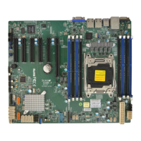
X10SRM-F/-TF
REV:1.01
Designed in the USA
SRW5
SRW4
SRW3
JVRM2
JVRM1
JOH1
JD1
1
1. iPass
2. M.2
2
M.2 Slot
The X0SRM-F/-TF motherboard contains one M.2 socket at JMD1. M.2 was formerly Next
Generation Form Factor (NGFF) and serves to replace mini PCI-E and mSATA. M.2 allows
for a variety of card sizes, increased functionality, and spatial efciency. The M.2 socket on
the motherboard supports PCI-E 2.0 x4 SSD (20Gb/s) cards in the 22x42mm, 22x80mm,
and 22x110mm form factors.
iPass connector
The X0SRM-F/-TF motherboard contains an iPass connector at JS1. This slim connector
houses four I-SATA connections. Connect devices to JS1 using an internal mini-SAS to SATA
cable (model SFF-8087) (SMC P/N: CBL-0097L-03 or CBL-0288L-01).
 Loading...
