60
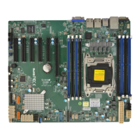
X10SRM-F/-TF User Manual
IPMI_LAN
USB0/1
LAN1
LAN2
USB6/7
(3.0)
JPL1
JSTBY1
JPG1
JTPM1
COM2
COM1
FAN4
JF1
JPH1
JPV1
JPW1
FAN1
JPI2C1
FAN2
FAN3
FANA
JPUSB1
USB10 (3.0)
USB8/9 (3.0)
USB4/5
I-SGPIO2
I-SGPIO1
JS1
JL1
USB2/3
JP3
JWD1
JPME2
JI2C2
JI2C1
JPB1
JBT1
BT1
JMD1
JNVI2C1
JIPMB1
LEDBMC
LEDPWR
LE8
LE1
JUIDB1
VGA
JPCIE4
JPCIE5
JPCIE6
CPU1 SLOT6 PCI-E 3.0 X16
CPU1 SLOT5 PCI-E 3.0 X8
CPU1 SLOT4 PCI-E 3.0 X8
FAN5
I-SATA3
SP1
I-SATA2
I-SATA1
I-SATA0
I-SATA5
I-SATA4
JSD2
JSD1
JPH2
DIMMA1
DIMMB1
DIMMD1
DIMMC1
CLOSE 1st
OPEN 1st
MAC CODE
BAR CODE BAR CODE
CPU
INTEL PCH
LAN
CONTROLLER
X10SRM-F/-TF
REV:1.01
Designed in the USA
SRW5
SRW4
SRW3
JVRM2
JVRM1
JOH1
JD1
1
1. SMBus to PCI Slots
2. BMC Enabled
2
SMBus to PCI Slots
Use jumpers JI
2
C1 and JI
2
C2 to connect the System Management Bus (I
2
C) to PCI-Express
slots to improve PCI performance. These two jumpers should be set at the same time. See
the table below for jumper settings. The default setting is Disabled.
I
2
C for PCI-E Slots
Jumper Settings
Jumper Setting Denition
Pins 1-2 Enabled
Pins 2-3 Disabled
BMC Enabled
Jumper JPB1 allows you to enable the embedded ASpeed AST2400 Baseboard Management
Controller (BMC) to provide IPMI 2.0/KVM support on the motherboard. Refer to the table
below for jumper settings. The default setting is BMC Enable.
BMC Enable
Jumper Settings
Jumper Setting Denition
Pins 1-2 BMC Enabled
Pins 2-3 Normal (Default)
 Loading...
