31
Chapter 2: Installation
DESIGNED IN USA
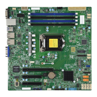
X13SCL-IF
REV:1.01
BAR CODE
BIOS LICENSE
JL1
JSMB1
JTPM1
I-SATA4
I-SATA5
BT1
JSLIM2
JSLIM1
C262
JPCIE1
JD1
LED3
LEDM1
JPI2C1
JMD1_SRW1
JPW2
FANA
FAN3
FAN2
FAN1
JF1
JPW1
JMD1
JBT1
JPME2
JNS1
JRF1
JPL1
JWD1
JPG1
MH4
MH3
MH2
MH1
JUIDB1
LED1
LED2
PCIe 4.0 x4
PCIe 4.0 x4 / SATA x4
CMOS CLEAR
2-3: NVMe
1-2: SATAJNS1:
LEDPWR
LEDBMC
USB4/5 (3.2(5Gb))
USB2/3 (3.2(5Gb))
COM1
PCIe 4.0 x4
JMD1:M.2-C
VGA
LAN1/2
JL1: CHASSIS INTRUSION
BMC_LAN
USB0/1
:SMBus1
:PWR I2C
1-4:SPEAKER
1-2:ENABLE
2-3:DISABLE
JPL2:LAN2
2-3:DISABLE
1-2:ENABLE
JPL1:LAN1
ON
PWR
RST
JF1:
NIC2
FF
OH
X
NIC1
LED
PWR
LED
HDD
CPU SLOT7 PCIe 5.0 x16 (IN x16)
DIMMA1
DIMMB1
2-3:ME MANUFACTURING MODE
JWD1:WATCH DOG
1-2:RST
2-3:NMI
1-2:ENABLE
2-3:DISABLE
JPG1:VGA
JPME2:
1-2:NORMAL
CPU
JTPM1:TPM/PORT80
BMC
Controller
DIMM Installation
1. Insert DIMM modules in the following
order: DIMMA1 and DIMMB1. For the
system to work properly, use memory
modules of the same type and speed.
2. Align the DIMM module key with the
receptive point on the single-latch DIMM
slot.
3. Push the release tab outwards to unlock
the slot.
4. Align the notch on the end of the module
against the receptive point on the end of
the slot.
5. Press both ends of the module straight
down into the slot until the module snaps
into place.
6. Push the release tab to the lock position to
secure the module into the slot.
DIMM Removal
Press the release tab on one end of the DIMM
module to unlock it. Once the DIMM module
is loosened, remove it from the memory slot.
Release Tab
Notch
Press both notches
straight down into
the memory slot.
Receptive Point

 Loading...
