43
Chapter 2: Installation
DESIGNED IN USA
X13SCL-IF
REV:1.01
BAR CODE
BIOS LICENSE
JL1
JSMB1
JTPM1
I-SATA4
I-SATA5
BT1
JSLIM2
JSLIM1
C262
JPCIE1
JD1
LED3
LEDM1
JPI2C1
JMD1_SRW1
JPW2
FANA
FAN3
FAN2
FAN1
JF1
JPW1
JMD1
JBT1
JPME2
JNS1
JRF1
JPL1
JWD1
JPG1
MH4
MH2
MH1
JUIDB1
LED1
LED2
PCIe 4.0 x4
CMOS CLEAR
2-3: NVMe
1-2: SATAJNS1:
LEDPWR
LEDBMC
USB4/5 (3.2(5Gb))
USB2/3 (3.2(5Gb))
COM1
PCIe 4.0 x4
JMD1:M.2-C
VGA
LAN1/2
JL1: CHASSIS INTRUSION
BMC_LAN
USB0/1
:SMBus1
:PWR I2C
1-4:SPEAKER
1-2:ENABLE
2-3:DISABLE
JPL2:LAN2
2-3:DISABLE
1-2:ENABLE
JPL1:LAN1
ON
PWR
RST
JF1:
NIC2
FF
OH
X
NIC1
LED
PWR
LED
HDD
CPU SLOT7 PCIe 5.0 x16 (IN x16)
DIMMA1
DIMMB1
2-3:ME MANUFACTURING MODE
JWD1:WATCH DOG
1-2:RST
2-3:NMI
1-2:ENABLE
2-3:DISABLE
JPG1:VGA
JPME2:
1-2:NORMAL
CPU
JTPM1:TPM/PORT80
BMC
Controller
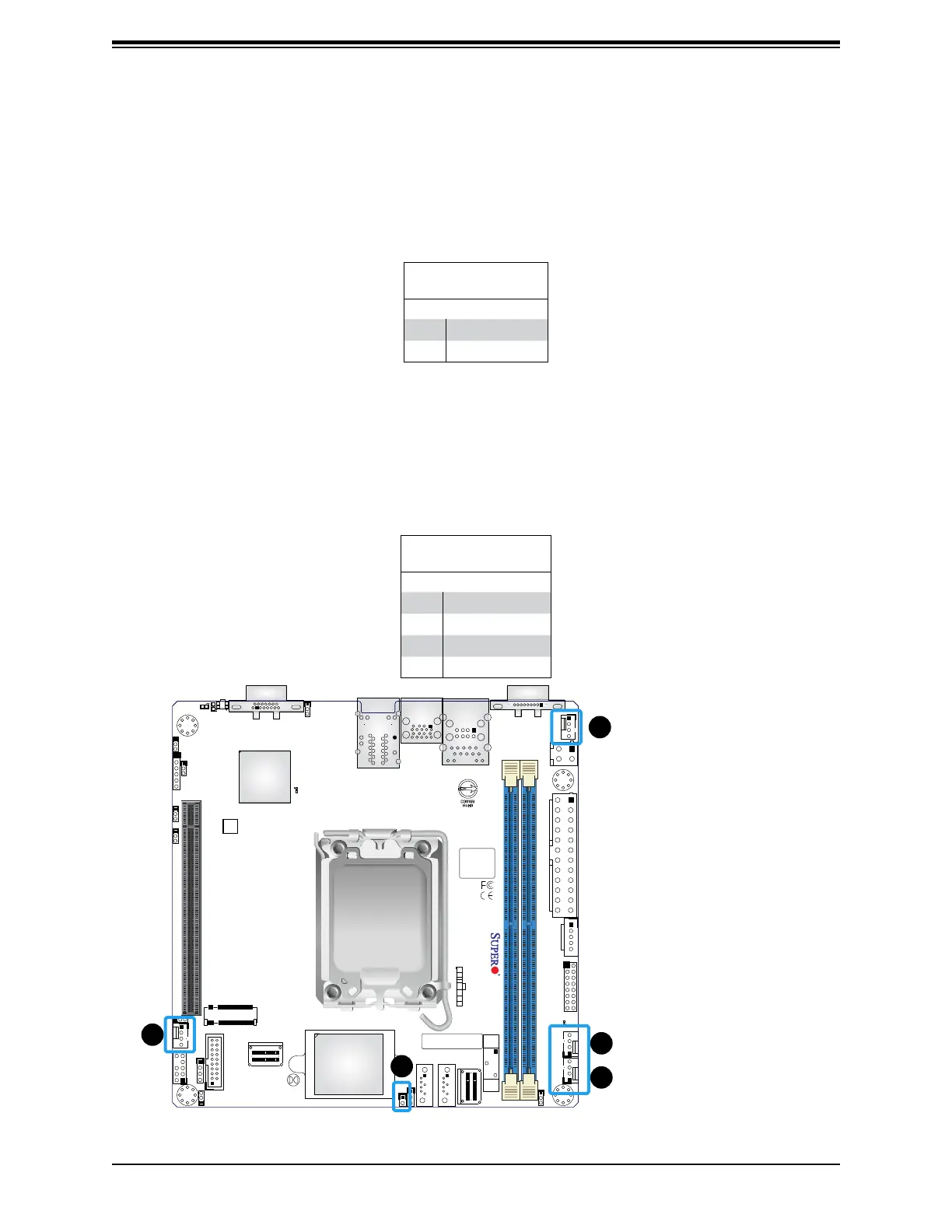
Fan Headers
There are four 4-pin fan headers (FAN1–FAN3, FANA) on the motherboard. All these 4-pin
fan headers are backwards compatible with the traditional 3-pin fans. However, fan speed
control is available for 4-pin fans only by Thermal Management via the Hardware Monitoring
through the BMC. Refer to the table below for pin denitions.
Headers
Fan Header
Pin Denitions
Pin# Denition
1 Ground (Black)
2 +12 V (Red)
3 Tachometer
4 PWM_Control
1
2
1. Chassis Intrusion
2. FAN1
3. FAN2
4. FAN3
5. FANA
Chassis Intrusion
A Chassis Intrusion header is located at JL1 on the motherboard. Attach the appropriate cable
from the chassis to be informed of a chassis intrusion when the chassis is opened. Refer to
the table below for pin denitions.
Chassis Intrusion
Pin Denitions
Pin# Denition
1 Intrusion Input
2 Ground
3
5
4
 Loading...


