Chapter 2: Installation
2-13
Power Button
OH/Fan Fail LED
1
NIC1 LED
Reset Button
2
HDD LED
Power LED
Reset
PWR
Vcc
Vcc
Vcc
Vcc
Ground
Ground
1920
Vcc
X
Ground
NMI
X
Vcc
PWR Fail LED
NIC2 LED
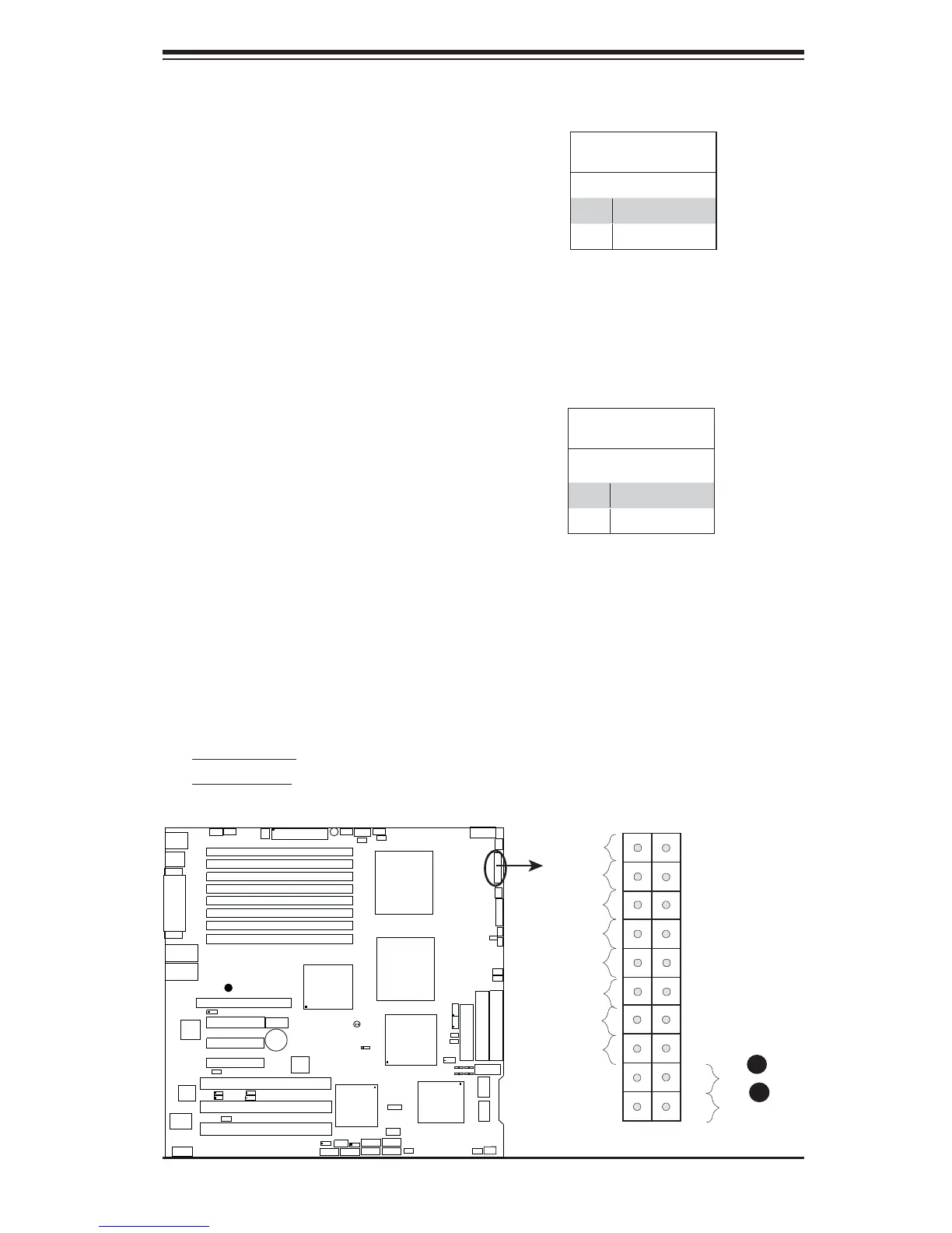
Power Button
The Power Button connection is located
on pins 1 and 2 of JF1. Momentarily con-
tacting both pins will power on/off the sys-
tem. This button can also be confi gured
to function as a suspend button (with a
setting in the BIOS - see Chapter 4). To
turn off the power when set to suspend
mode, press the button for at least 4
seconds. Refer to the table on the right
for pin defi nitions.
Power Button
Pin Defi nitions (JF1)
Pin# Defi nition
1 Signal
2 +3V Standby
Reset Button
The Reset Button connection is located
on pins 3 and 4 of JF1. Attach it to the
hardware reset switch on the computer
case. Refer to the table on the right for
pin defi nitions.
Reset Button
Pin Defi nitions (JF1)
Pin# Defi nition
3 Reset
4 Ground
A. Reset Button
B. PWR Button
A
B
GLAN1
®
JLAN1
S
UPER
GLAN2
F
a
n
1
8-pinPWR
FP Control
SPK
PW LED
JOH1
F
an
3
IDE
1
F
l
o
p
p
y
F
a
n
4
S
A
T
A
1
S
A
T
A
0
U
SB2
/3
SMB
P
C
I
-
X
1
0
0
M
H
z
Z
C
R
P
C
I
-
X
1
3
3
M
H
z
J
W
D
B
a
ttery
VG
A
PCI
-E xp
x8
Nor
t
h
B
r
idge
VGA
COM
1
USB0/1
KB/
M
ouse
Fan
6
Fan5
AT
X
P
WR
4-P
i
n
P
W
R
J3P
Parrallel
Port
24-
P
i
n
J
P
G1
SAS CTRLR
Adaptec 9410W
C
P
U
1
C
P
U
2
P
X
H
D
IMM
1
A (B a
nk
1
)
Fan7
JAR
PSF
F
a
n
2
C
o
m
p
a
c
t
F
la
s
h
LE1
Fa
n8
J
C
F
1
J
W
F1
S
A
T
A
3
S
A
T
A
2
S
A
T
A
4
S
A
T
A
5
JL1
JK
1
S
l
o
t1
S
l
o
t2
S
l
o
t3
P
C
I
-
X
1
3
3
M
H
z
S
l
o
t
4
J
PL
1
J
P
L
2
S
l
o
t5
PCI-Exp x4
S
l
o
t6
PCI-Exp x8
SEPC
SIMLP IPMI
S
l
o
t7
DIMM
1B (B ank
1)
DIMM
2
A (B a
nk
2
)
DIMM
2B (Bank
2
)
DI
M
M
3
A (B a
n
k
3
)
DIMM
3B (Bank
3)
D
IM
M
4
A (B a
nk
4
)
DIMM
4B (Bank 4)
J7
JB
T
1
U
S
B
4
JWO
R
JCO
M
2
W
OL
S
I
/
O
JP1
LAN
CTRLR
J27
J28
S
G
P
I
O
2
SMBPS
C
TR
LR
Inte
l 5
0
0
0
P
South B
r
id
g
e
Xe
on D
ual
Core
Xe
o
n
D
ual
Core
JS
A
3
SA
S0-3
S
A
S4-7
J
P
S1
Int
e
l E S B 2
S
G
P
I
O
1
B
P
LE
D
C
on
X7DB3
B
I
O
S
Buzzer