Chapter 2: Installation
2-15
GLAN1
®
JLAN1
S
UPE R
GLAN2
F
a
n
1
8-pinPWR
FP C ontrol
SPK
PW LED
JOH1
Fa
n3
ID
E
1
Floppy
Fa
n4
S
ATA
1
S
ATA
0
USB2/
3
S
MB
P
CI-
X
1
00
MHz
ZCR
P
C
I
-
X
13
3 M
H
z
J
WD
Ba
ttery
V
GA
P
C
I-E
x
p
x
8
N
orth Bridge
V
G
A
C
O
M1
USB0
/
1
KB
/
Mo
u
se
F
an6
Fan
5
ATX PW
R
4
-
P
in
PWR
J3P
Parrallel
Port
24-Pi
n
J
P
G
1
SAS CTRLR
Adaptec 9410W
C
PU
1
C
PU
2
P
X
H
DIMM 1
A (Bank 1)
F
a
n
7
JAR
PSF
F
an2
C
o
mp
act F
l
ash
LE1
F
an
8
J
CF1
J
W
F
1
S
A
T
A3
S
A
T
A2
S
ATA
4
S
ATA
5
J
L
1
J
K
1
S
lot1
S
lo
t
2
S
l
o
t
3
P
C
I
-
X
13
3
MH
z
S
lot4
JPL1
J
P
L2
S
lot5
PCI-Exp x4
S
lot6
PCI-Exp x8
SEPC
SIMLP IPMI
S
lot7
D
IM
M
1
B (Bank 1
)
D
IMM
2
A (Ba
n
k
2
)
DIMM
2
B (Bank 2)
DIM
M
3A
(
B
a
n
k
3)
DIMM 3
B (
B
ank 3)
DIMM 4
A (B
a
n
k
4)
DI
M
M
4
B (Bank
4)
J
7
J
B
T
1
U
SB
4
JWO
R
JCOM2
WOL
S
I/O
JP1
L
A
N
C
T
RL
R
J27
J2
8
SGPIO
2
SMBPS
CTRLR
Inte
l
50
00P
S
o
u
t
h B ridge
Xeon Dual Core
X
eo
n
D
u
a
l Core
J
SA3
SA
S0
-
3
S
A
S4-
7
J
P
S1
I
n
t
e
l E S B 2
SGPIO
1
B
P
LED
C
o
n
X7DB
3
B
IOS
Buzzer
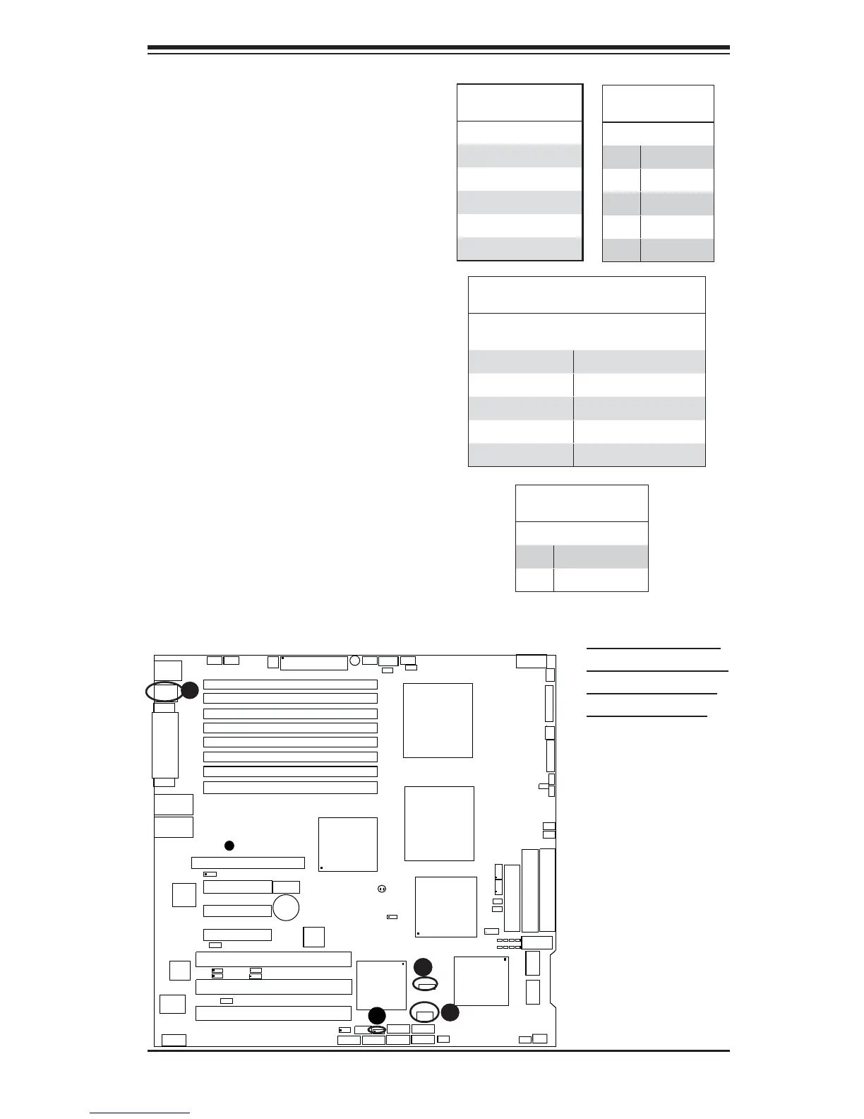
Universal Serial Bus (USB)
There are fi ve USB 2.0 (Universal Se-
rial Bus) ports/headers on the moth-
erboard. Two of them are Back Panel
USB ports (USB#0/1:JUSB1), and
the other three are Front Panel USB
headers (USB#2/3:JUSB2, USB#4:
JUSB3). See the tables on the right
for pin defi nitions.
Chassis Intrusion
A Chassis Intrusion header is located
at JL1 on the motherboard. Attach the
appropriate cable from the chassis to
inform you of a chassis intrusion when
the chassis is opened.
Chassis Intrusion
Pin Defi nitions (JL1)
Pin# Defi nition
1 Intrusion Input
2 Ground
A
B
C
A. Backpanel USB 0-1
B. Front Panel USB 2-3
C. Front Panel USB 4
D. Chassis Intrusion
Back Panel USB
(USB0/1)
Pin# Defi nitions
1 +5V
2 PO-
3 PO+
4 Ground
5 N/A
Front Panel USB
Pin Defi nitions (USB4)
USB4
Pin # Defi nition
USB5
Pin # Defi nition
1 +5V 1 +5V
2 PO- 2 PO-
3 PO+ 3 PO+
4 Ground 4 Ground
5 Key 5 No connection
Front Panel USB
(USB2/3)
Pin# Defi nition
1 +5V
2 Data-
3 Data+
4 Ground
5NA