2-22
X7DB3 User's Manual
GLAN1
®
JLAN1
S
UPE R
GLAN2
F
a
n
1
8-pinPWR
FP C ontrol
SPK
PW LED
JOH1
Fa
n3
ID
E
1
Floppy
Fa
n4
S
ATA
1
S
ATA
0
USB2/
3
S
M
B
P
CI-
X
1
00
MHz
ZCR
P
C
I
-
X
1
3
3 M
H
z
J
WD
Ba
ttery
V
GA
P
C
I-
Exp x8
Nort
h B ridge
V
G
A
C
O
M1
USB0/1
KB
/
Mo
u
se
F
an6
F
a
n
5
ATX PWR
4
-
P
in
PWR
J3P
Parrallel
Port
24-Pi
n
J
P
G
1
SAS CTRLR
Adaptec 9410W
C
PU
1
C
PU
2
P
X
H
DIMM 1
A (Ban
k
1
)
F
a
n
7
JAR
PSF
F
an2
C
o
mp
act F
las h
LE1
F
an
8
J
CF1
JWF
1
S
AT
A3
S
AT
A2
S
ATA
4
S
ATA
5
J
L
1
J
K1
S
lot1
S
lo
t
2
S
lo
t
3
P
C
I
-
X
13
3 M
H
z
S
lot4
J
P
L1
J
P
L2
S
lot5
PCI-Exp x4
S
lot6
PCI-Exp x8
SEPC
SIMLP IPMI
S
lot7
DIMM 1
B (Bank 1)
D
IMM
2
A (Ba
n
k
2)
DI
M
M
2
B (Ba
nk 2)
DIMM 3
A
(
B
a
n
k
3)
DIMM 3
B
(
B
ank 3)
DIMM 4
A (Ban
k
4)
DIMM 4
B (Bank 4)
J7
J
B
T1
U
SB
4
JW
O
R
J
C
O
M
2
WOL
S
I/O
JP1
L
A
N
C
T
R
L
R
J27
J28
SGPIO
2
SMBPS
CTRLR
Inte
l
50
00P
S
o
u
t
h
Bridge
Xeon Dual Core
X
eo
n
Du
al
C
ore
J
S
A
3
SA
S0
-
3
S
A
S4-
7
JPS1
I
nte
l E S B 2
SGPIO
1
B
PLE
D
C
o
n
X7D
B3
B
IOS
Buzzer
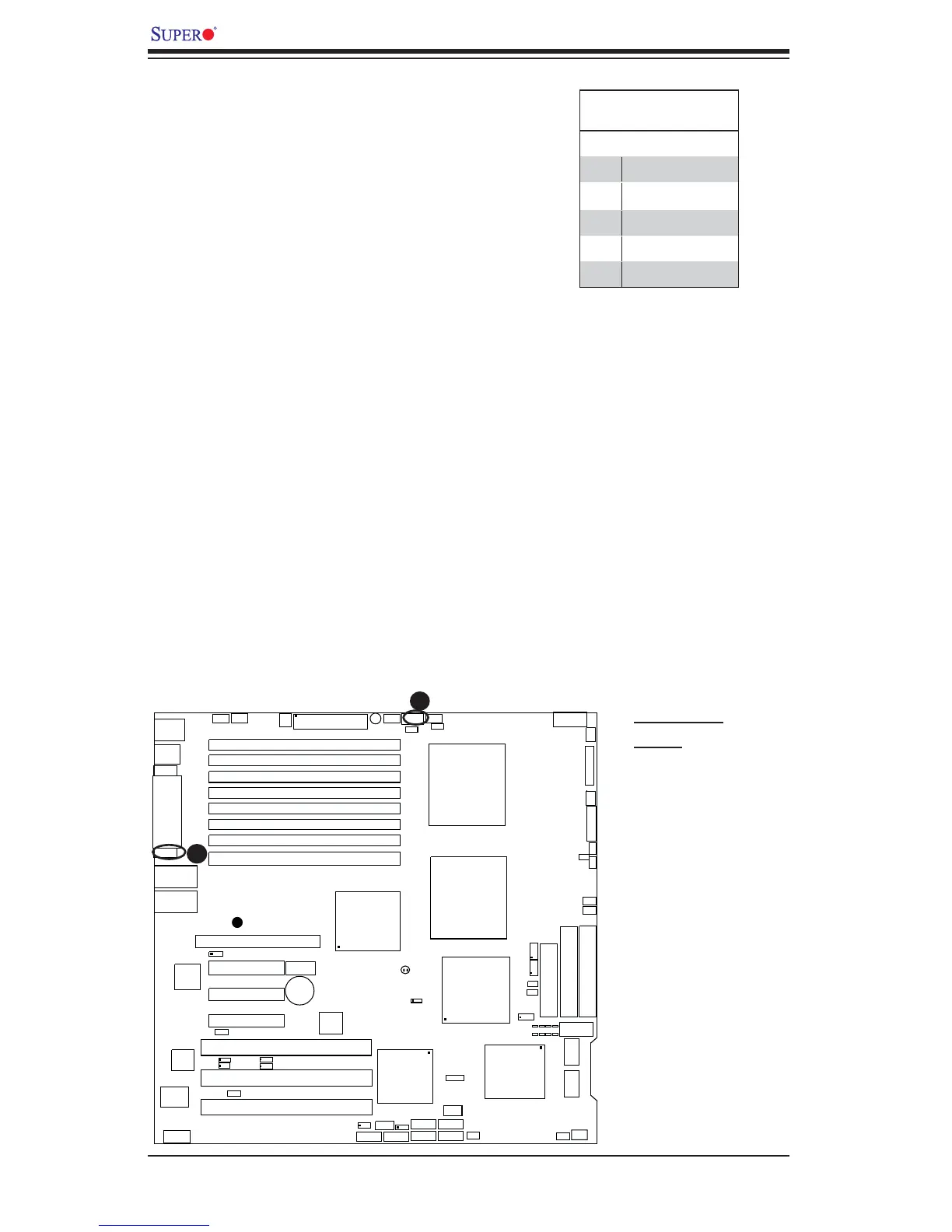
Power SMB (I
2
C) Connector
Power SMB (I
2
C) Connector (J17)
monitors the status of PWR supply,
fan and system temperature. See the
table on the right for pin defi nitions.
PWR SMB
Pin Defi nitions
Pin# Defi nition
1 Clock
2 Data
3 PWR Fail
4 Ground
5 +3.3V
A
B
A. PWR SMB
B. VGA
VGA Connector
A VGA connector (JG1) is located next
to COM1 port on the IO backplane.
Refer to the board layout below for
the location.