Chapter 2: Installation
2-33
GLAN1
®
JLAN1
S
UPE R
GLAN2
F
a
n
1
8-pinPWR
FP C ontrol
SPK
PW LED
JOH1
Fa
n3
ID
E
1
F
l
oppy
Fa
n4
S
ATA
1
S
ATA
0
USB2/
3
S
MB
P
CI-
X
1
00
M
Hz
ZCR
P
C
I
-
X
13
3 M
H
z
J
W
D
Ba
ttery
V
GA
P
C
I-E
x
p
x
8
N
orth B ridge
V
G
A
C
O
M1
USB 0
/
1
KB
/
Mo
u
se
F
an6
Fan
5
ATX PW
R
4
-
P
in
PWR
J3P
Parrallel
Port
24-Pi
n
J
P
G
1
SAS CTRLR
Adaptec 9410W
C
PU
1
C
PU
2
P
X
H
DIMM 1
A (Ban
k
1)
F
a
n
7
JAR
PSF
F
an2
C
o
m
p
act F
l
as
h
LE1
F
an
8
J
CF1
J
W
F
1
S
A
T
A3
S
A
T
A2
S
ATA
4
S
ATA
5
J
L
1
J
K1
S
lot1
S
lo
t
2
S
l
o
t
3
P
C
I
-
X
13
3
M
H
z
S
lot4
J
P
L1
J
P
L2
S
lot5
PCI-Exp x4
S
lot6
PCI-Exp x8
SEPC
SIMLP IPMI
S
lot7
D
IM
M
1
B (Bank 1)
D
IMM
2
A (Ba
n
k
2
)
DIMM
2
B (Bank 2)
DIM
M
3A
(
B
a
n
k
3)
DIMM 3
B (
B
a
nk 3)
DIMM 4
A (B
a
nk 4)
DI
M
M
4
B (Bank
4)
J7
J
B
T
1
U
SB
4
JWO
R
JCOM2
WOL
S
I/O
JP1
L
A
N
C
T
R
L
R
J27
J2
8
S
GPIO2
SMBPS
C
TRL
R
Inte
l
50
00P
S
o
u
t
h B ridge
Xeon Dual Core
X
eo
n
D
u
a
l Core
J
SA3
S
A
S0-
3
SAS4-
7
J
P
S1
I
n
t
e
l E S B 2
S
GPIO1
B
PLED
C
o
n
X7DB
3
B
IOS
Buzzer
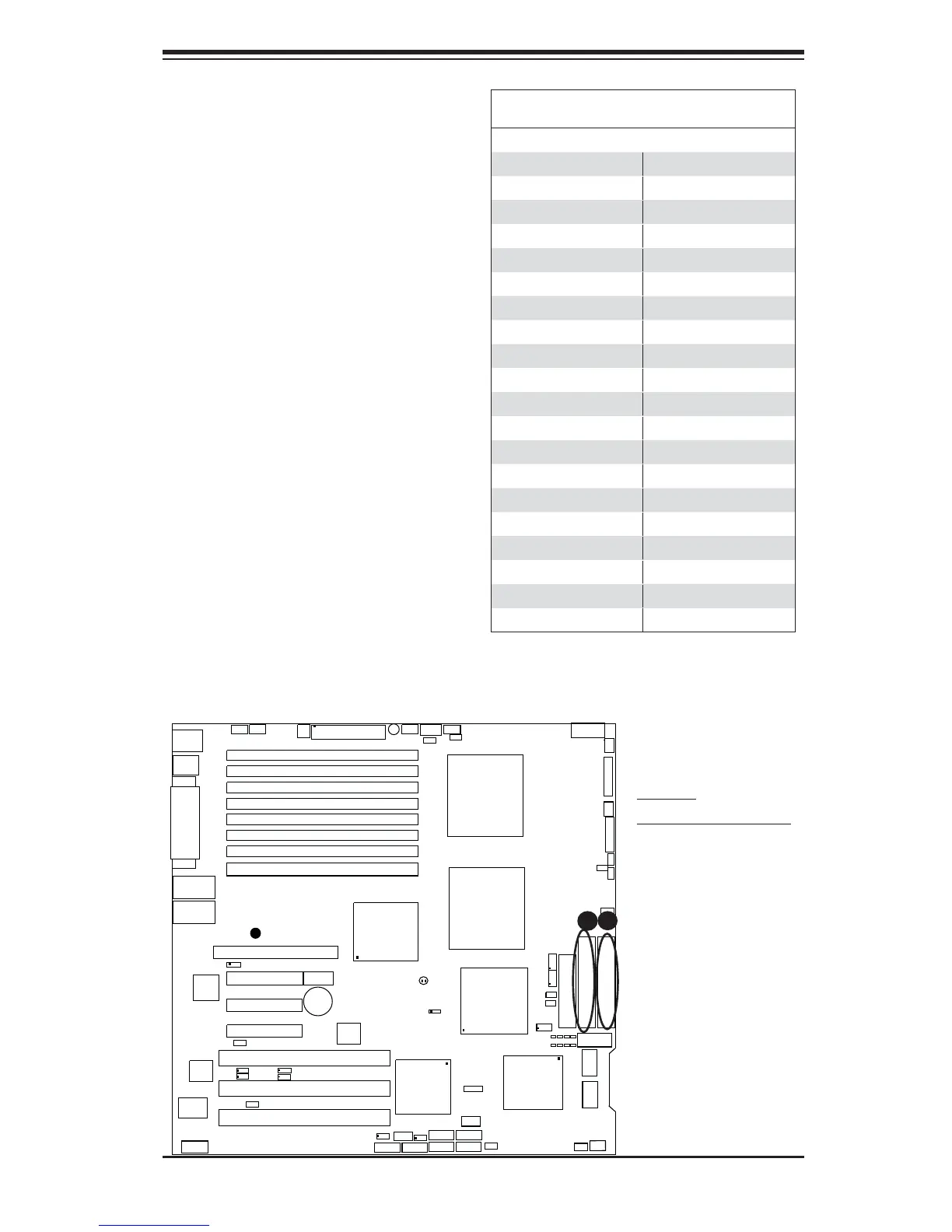
IDE Drive Connectors
Pin Defi nitions
Pin# Defi nition Pin # Defi nition
1 Reset IDE 2 Ground
3 Host Data 7 4 Host Data 8
5 Host Data 6 6 Host Data 9
7 Host Data 5 8 Host Data 10
9 Host Data 4 10 Host Data 11
11 Host Data 3 12 Host Data 12
13 Host Data 2 14 Host Data 13
15 Host Data 1 16 Host Data 14
17 Host Data 0 18 Host Data 15
19 Ground 20 Key
21 DRQ3 22 Ground
23 I/O Write 24 Ground
25 I/O Read 26 Ground
27 IOCHRDY 28 BALE
29 DACK3 30 Ground
31 IRQ14 32 IOCS16
33 Addr1 34 Ground
35 Addr0 36 Addr2
37 Chip Select 0 38 Chip Select 1
39 Activity 40 Ground
A
B
IDE Connectors
There are two IDE Connectors (JIDE1:
Blue, JIDE2: White) on the moth-
erboard. The blue IDE connector
(JIDE1) is designated the Primary
IDE Drive. The white IDE connector
(JIDE2) is designated the Second-
ary IDE Drive, reserved for Compact
Flash Card use only. (See the note
below.) See the table on the right for
pin defi nitions.
Note: JIDE2 (the white slot) is re-
served for Compact Flash Card only.
Do not use it for other devices. If
JIDE2 is populated with a Compact
Flash Card, JIDE1 (the blue slot) will
be available for one device only. For
the Compact Flash Card to work prop-
erly, you will need to connect a power
cable to JWF1 fi rst.
A. IDE#1
B. Compact Flash Card