Chapter 2: Installation
2-11
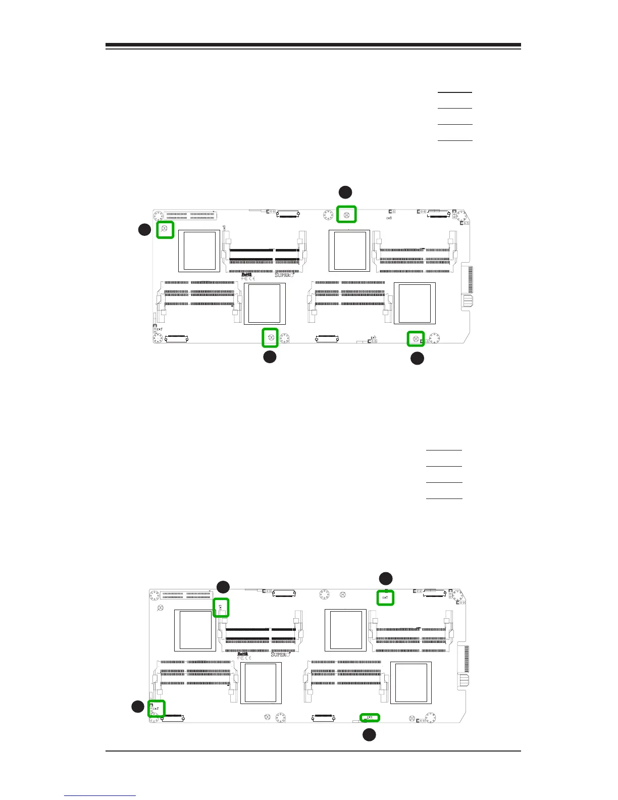
Clear CMOS (JBT1~4)
JBT is used to clear CMOS. Instead of pins,
this "jumper" consists of contact pads to pre-
vent accidental clearing of CMOS. To clear
CMOS, use a metal object such as a small
screwdriver to touch both pads at the same
time to short the connection.
B1SA4-F
J2
J22
JKVM2
JKVM3
JKVM4
JKVM1
MH2
MH1
J20
LED1
LED2
LED3
LED4
JBT1
JBT2
JBT3
JBT4
JWD1
JWD3
J5
JWD4
J21
J18
JWD2
Q55
MH4
MH5
MH3
C1272
P3-JBT1
P4-JBT1
P1
P2-JBT1
JWD1
P1-JWD1
P2-JWD1:
P3-JWD1
P4-JWD1
WATCH
1-2:RST
2-3:NMI
DOG
WATCH1-2:RST
2-3:NMI
DOG
WATCH
1-2:RST
2-3:NMI
DOG
DOGWATCH
2-3:NMI
1-2:RST
P4-DIMMB1
P4-DIMMA1
P3-DIMMA1
P3-DIMMB1
P2-DIMMB1
P2-DIMMA1
P1-DIMMB1
P1-DIMMA1
CPU2
CMOS
CLEAR
CMOSCLEAR
CMOS
CLEAR
CMOS
CLEAR
A
B
C
D
A. JBT1
B. JBT2
C. JBT3
D. JBT4
BMC Heartbeat (LED1~4)
When blinking,the BMC Heartbeat LED is an
indicator that the onboard Baseboard Manage-
ment Controller (BMC) is working normally.
There is one LED indicator for each node on
the motherboard.
B1SA4-F
J2
J22
JKVM2
JKVM3
JKVM4
JKVM1
MH2
MH1
J20
LED1
LED2
LED3
LED4
JBT1
JBT2
JBT3
JBT4
JWD1
JWD3
J5
JWD4
J21
J18
JWD2
Q55
MH4
MH5
MH3
C1272
P3-JBT1
P4-JBT1
P1
P2-JBT1
JWD1
P1-JWD1
P2-JWD1:
P3-JWD1
P4-JWD1
WATCH
1-2:RST
2-3:NMI
DOG
WATCH1-2:RST
2-3:NMI
DOG
WATCH
1-2:RST
2-3:NMI
DOG
DOGWATCH
2-3:NMI
1-2:RST
P4-DIMMB1
P4-DIMMA1
P3-DIMMA1
P3-DIMMB1
P2-DIMMB1
P2-DIMMA1
P1-DIMMB1
P1-DIMMA1
CPU2
CMOS
CLEAR
CMOSCLEAR
CMOS
CLEAR
CMOS
CLEAR
A
B
C
D
A. LED1
B. LED2
C. LED3
D. LED4
2-6 Onboard Indicators