2-20
X8DTU/X8DTU-F User's Manual
Power Button
1
NIC1 (Link) LED
Reset Button
2
HDD LED
FP PWR LED
Reset
PWR
3.3V
ID_UID/3.3V SB
Ground
Ground
1920
3.3 V
Key
Ground
NMI
PWR Fail LED
NIC2 (Link) LED
Blue+(OH/Fan Fail/PWR
Fail/Blue_UID LED
Red+(Blue LED_
Cathode_UID)
NIC1 (Activity) LED
NIC2 (Activity) LED
Key
X8DTU/-F
Rev. 2.01
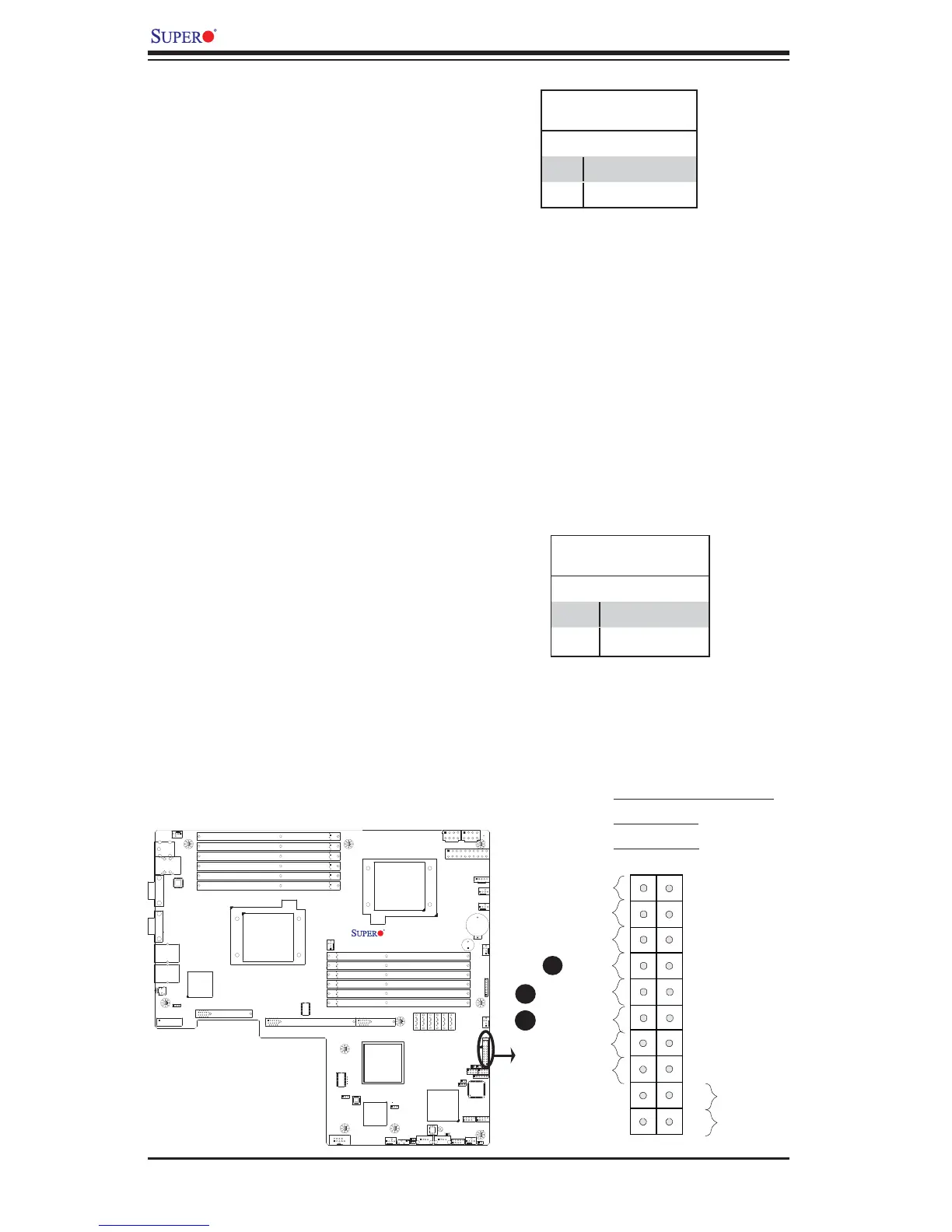
NIC1/NIC2 LED Indicators
The NIC (Network Interface Control-
ler) LED connection for GLAN port 1 is
located on pins 11 and 12 of JF1, and
the LED connection for GLAN Port 2
is on Pins 9 and 10. Attach the NIC
LED cables to display network activity.
Refer to the table on the right for pin
defi nitions.
HDD LED/UID Switch
The HDD/UID LED connection is lo-
cated on pins 13 and 14 of JF1. Attach
a hard drive LED cable here to display
disk activity status (for any hard drive
activities on the system, including
Serial ATA activities). Connect a UID
switch cable to use UID switch con-
nection. The front UID switch works
in conjunction with UID LED located at
Pins 7/8. Refer to Page 2-18 for more
UID switch/LED information. See the
table on the right for pin defi nitions.
HDD LED/UID Switch
Pin Defi nitions (JF1)
Pin# Defi nition
13 UID Switch/3,3V
14 HDD Active
GLAN1/2 LED
Pin Defi nitions (JF1)
Pin# Defi nition
9/11 NIC Activity
10/12 NIC Link
A
B
C
A. HDD LED/UID Switch
B. NIC1 LED
C. NIC2 LED
 Loading...


