Chapter 2: Installation
2-25
KB/MS
Fan8
(CPU1Fan)
IPMI LAN
USB 0/1
COM1
PHY
VGA
LAN1
LAN2
LAN CTRL
BMC CTRL
BIOS
COM2
USB6
USB7
USB4/5
JTAG Of CPLD
JPI2C
P1-DIMM3A
P1-DIMM3B
P1-DIMM2A
P1-DIMM2B
P1-DIMM1A
P1-DIMM1B
P2-DIMM1B
P2-DIMM1A
P2-DIMM2B
P2-DIMM2A
P2-DIMM3B
P2-DIMM3A
LE2
JUIDB
JPL1
J10
UIOP
SXB2: PCI-E 2.0 x 8
SXB1: PCI-E 2.0 x 16
SXB3: PCI-E 2.0 x 8 in x 4 Slot
J1
J2
J3
JPG1
Fan6
IPMB
JI2C1
JBT1
J13
J14
J12
Fan5
JL1
USB2/3 JLPC1
CPU2
CPU1
Intel 5520
IOH]
Intel ICH10R
South Bridge
T-SGPIO2
T-SGPIO1
J17
JWD
JF1
JOH1
LE1
Fan4
Fan3
SP1
Buzzer
JBAT1
Battery
Fan2
Fan1
JPW1
JPW3
JPW2
JD1
I-SATA5
I-SATA4
I-SATA3
I-SATA2
I-SATA1
I-SATA0
X8DTU/-F
Fan7(CPU2 Fan)
FP CTRL
CPLD
PWRLED/SPK
Rev. 2.01
JPB
JI2C2
JP3
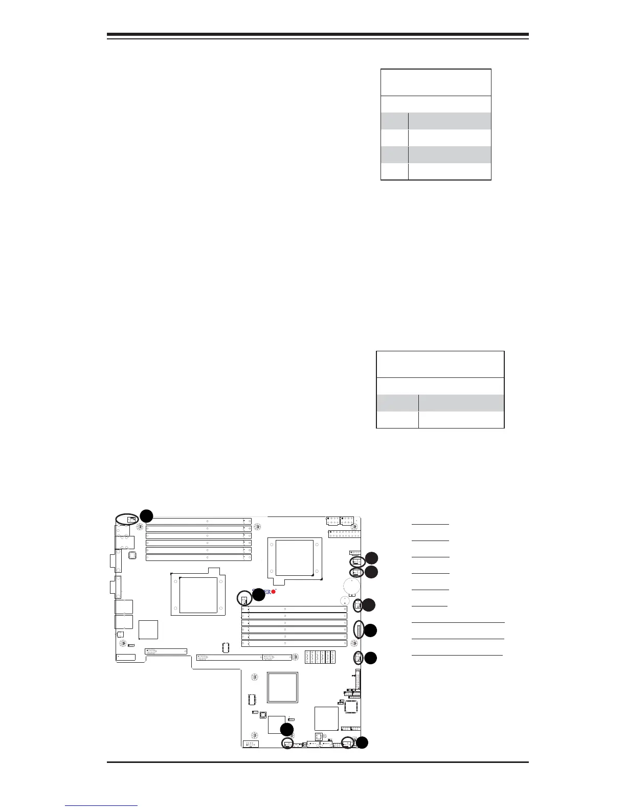
A. Fan 1
B. Fan 2
C. Fan 3
D. Fan 4
E. Fan 5
F. Fan 6
G. Fan 7 (CPU1 Fan)
H. Fan 8 (CPU2 Fan)
I. PWR LED/Speaker
Fan Headers
The X8DTU/X8DTU-F has six chassis/system
fan headers (Fan1 to Fan6) and two CPU fans
(Fan7/Fan8) on the motherboard. All these
4-pin fans headers are backward compatible
with the traditional 3-pin fans. However, fan
speed control is available for 4-pin fans only.
The fan speeds are controlled by a Hardware
Monitoring setting in the BIOS. (The Default
setting is Disabled.) See the table on the right
for pin defi nitions.
Fan Header
Pin Defi nitions
Pin# Defi nition
1 Ground
2 +12V
3 Tachometer
4 PWR Modulation
B
C
A
Speaker/Power LED Header
On the JD1 header, pins 1-3 are used for
power LED indication, and pins 4-7 are for
the speaker. See the table on the right for
speaker pin defi nitions. Please note that the
speaker connector pins (4-7) are for use with
an external speaker. If you wish to use the
onboard speaker, you should close pins 6-7
with a jumper.
Speaker/Power LED Con-
nector
Pin Setting Defi nition
Pins 6-7 Internal Speaker
Pins 4-7 External Speaker
I
H
 Loading...


