2-22
X8DTU/X8DTU-F User's Manual
X8DTU/-F
Rev. 2.01
Power Butt
1
NIC1 (Link) LED
Reset Butt
2
HDD LED
FP PWR LED
Reset
PWR
3.3V
ID_UID/3.3V SB
Ground
Ground
1920
3.3 V
Key
Ground
NMI
PWR Fail LED
NIC2 (Link) LED
Blue+(OH/Fan Fail/PWR
Fail/Blue_UID LED
Red+(Blue LED_
Cathode_UID)
NIC1 (Activity) L
NIC2 (Activity) L
Key
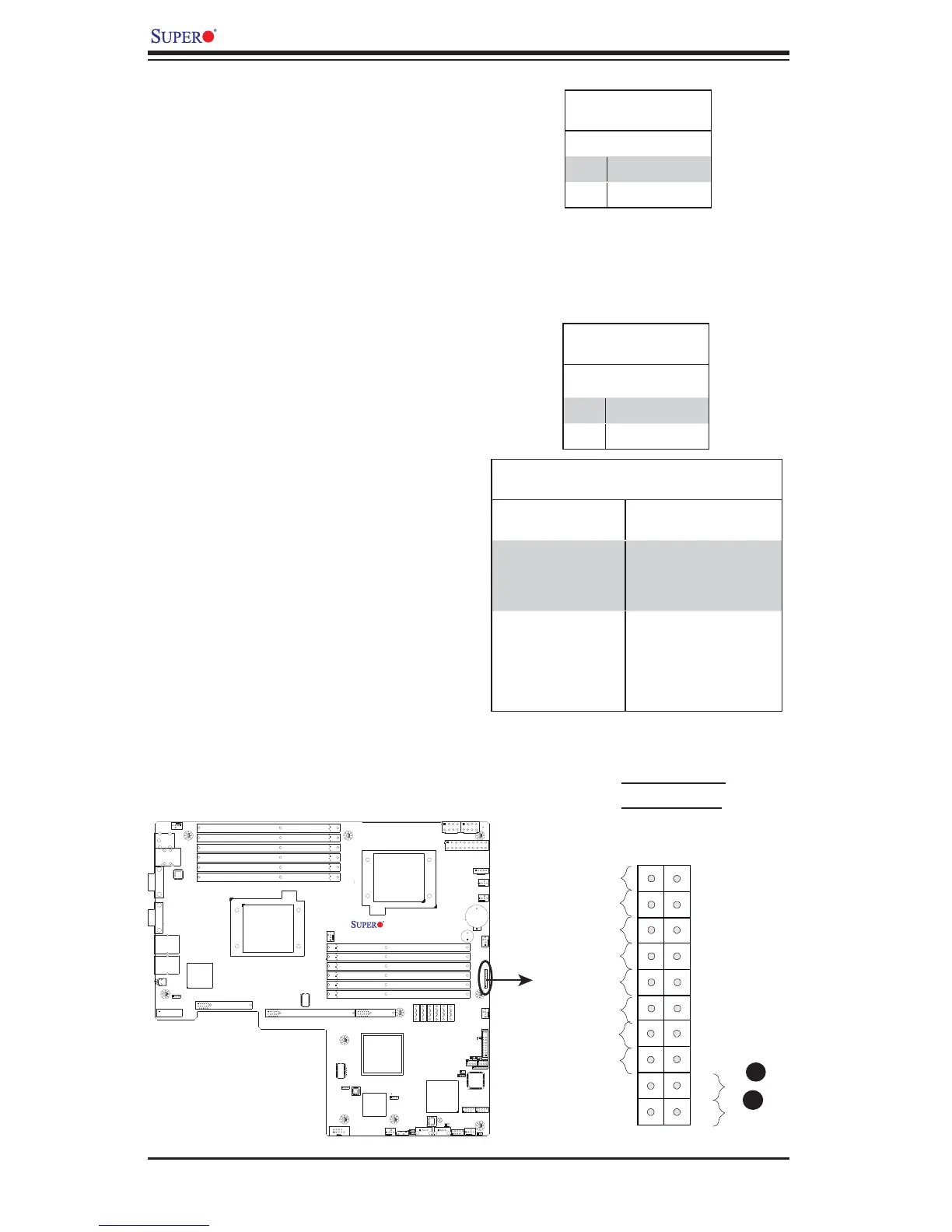
Power Button
The Power Button connection is located
on pins 1 and 2 of JF1. Momentarily
contacting both pins will power on/off the
system. This button works in conjunction
with the Power-Off setting in the BIOS
Advanced submenu. Refer to the tables
on the right for pin defi nitions.
Power Button
Pin Defi nitions (JF1)
Pin# Defi nition
1 Signal
2 +3V Standby
Reset Button
The Reset Button connection is located
on pins 3 and 4 of JF1. Attach it to a
hardware reset switch on the computer
case. Refer to the table on the right for
pin defi nitions.
Reset Button
Pin Defi nitions (JF1)
Pin# Defi nition
3 Reset
4 Ground
A. Reset Button
B. PWR Button
A
B
Power Button
Power On/Off Settings
PWR_Off Setting in
the BIOS:
PWR Activity on the
motherboard:
When PWR_Off is
set to Instant_Off
To power-on: Power is
turned on immediately
To pwer-off: PWR is
turned off immediately
When PWR_Off
is set to 4_second
suspend
To power-on: Power is
turned on immediately
To pwer-off: Short both
pins for 4 seconds or
longer to turn off the
power.
 Loading...


