Chapter 2: Installation
2-23
KB/MS
Fan8
(CPU1Fan)
IPMI LAN
USB 0/1
COM1
PHY
VGA
LAN1
LAN2
LAN CTRL
BMC CTRL
BIOS
COM2
USB6
USB7
USB4/5
JTAG Of CPLD
JPI2C
P1-DIMM3A
P1-DIMM3B
P1-DIMM2A
P1-DIMM2B
P1-DIMM1A
P1-DIMM1B
P2-DIMM1B
P2-DIMM1A
P2-DIMM2B
P2-DIMM2A
P2-DIMM3B
P2-DIMM3A
LE2
JUIDB
JPL1
J10
UIOP
SXB2: PCI-E 2.0 x 8
SXB1: PCI-E 2.0 x 16
SXB3: PCI-E 2.0 x 8 in x 4 Slot
J1
J2
J3
JPG1
Fan6
IPMB
JI2C1
JBT1
J13
J14
J12
Fan5
JL1
USB2/3 JLPC1
CPU2
CPU1
Intel 5520
IOH]
Intel ICH10R
South Bridge
T-SGPIO2
T-SGPIO1
J17
JWD
JF1
JOH1
LE1
Fan4
Fan3
SP1
Buzzer
JBAT1
Battery
Fan2
Fan1
JPW1
JPW3
JPW2
JD1
I-SATA5
I-SATA4
I-SATA3
I-SATA2
I-SATA1
I-SATA0
X8DTU/-F
Fan7(CPU2 Fan)
FP CTRL
CPLD
PWRLED/SPK
Rev. 2.01
JPB
JI2C2
JP3
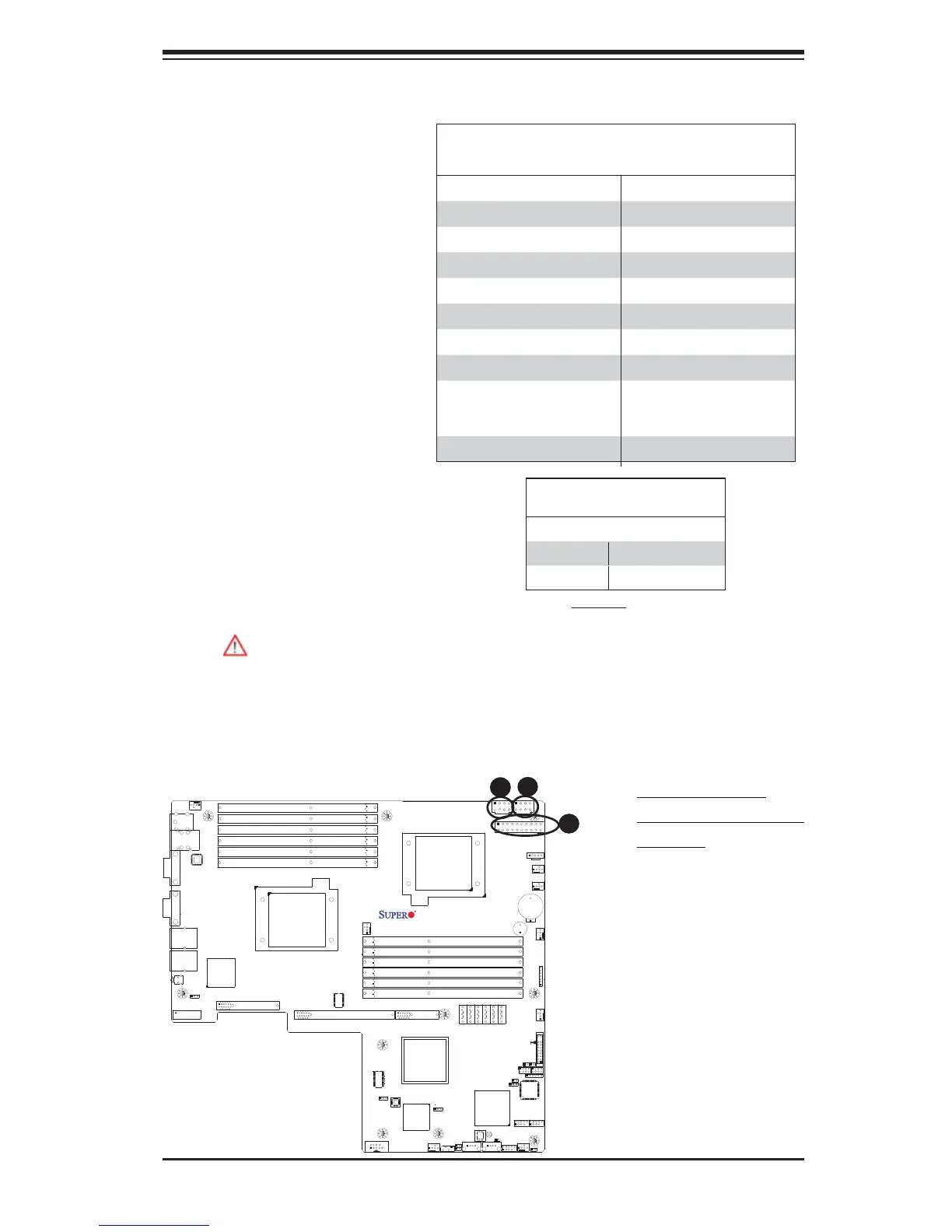
Warning: To prevent damage to your power supply or motherboard, please
use a power supply that contains a 20-pin and two 8-pin power connec-
tors. Be sure to connect these power connectors to the 20-pin and the two
8-pin power connectors on your motherboard for adequate power supply
to your system. Failure to do so will void the manufacturer warranty on
your power supply and motherboard.
ATX Power Connector
There are a 20-pin main power
supply connector(JPW1) and
two 8-pin CPU PWR con-
nectors (JPW2/JPW3) on the
motherboard. These power
connectors meet the SSI EPS
12V specifi cation.
Processor Power Connector
In addition to the Primary ATX
power connector, the 12V
8-pin CPU PWR connectors
at JPW2/JPW3 must also be
connected to your power sup-
ply. See the table on the right
for pin defi nitions.
12V 8-pin Power Connector
Pin Defi nitions
Pins Defi nition
1 through 4 Ground
5 through 8 +12V
A. 20-pin ATX PWR
B/C.8-pin Processor PWR
(Required)
B
C
2-6 Connecting Cables
(Required)
20-pin Main Power Connector Pin Defi nitions
Pin# Defi nition Wire Color Pin # Defi nition Wire Color
1 +3.3Vdc Orange 11 +3.3Vdc Orange
2 +3.3Vdc Orange 12 -12Vdc Blue
3 Ground Black 13 Ground Black
4 +5Vdc Red 14 PS-On Green
5 Ground Black 15 Ground Black
6 +5Vdc Red 16 Ground Black
7 Ground Black 17 Ground Black
8 PWR_OK Gray 18 -5Vdc White
9 +5Vdc VSB
Standby
Voltage
Purple 19 +5Vdc Red
10 +12Vdc Yellow 20 +5Vdc Red
 Loading...


