Chapter 2: Installation
2-27
KB/MS
Fan8
(CPU1Fan)
IPMI LAN
USB 0/1
COM1
PHY
VGA
LAN1
LAN2
LAN CTRL
BMC CTRL
BIOS
COM2
USB6
USB7
USB4/5
JTAG Of CPLD
JPI2C
P1-DIMM3A
P1-DIMM3B
P1-DIMM2A
P1-DIMM2B
P1-DIMM1A
P1-DIMM1B
P2-DIMM1B
P2-DIMM1A
P2-DIMM2B
P2-DIMM2A
P2-DIMM3B
P2-DIMM3A
LE2
JUIDB
JPL1
J10
UIOP
SXB2: PCI-E 2.0 x 8
SXB1: PCI-E 2.0 x 16
SXB3: PCI-E 2.0 x 8 in x 4 Slot
J1
J2
J3
JPG1
Fan6
IPMB
JI2C1
JBT1
J13
J14
J12
Fan5
JL1
USB2/3 JLPC1
CPU2
CPU1
Intel 5520
IOH]
Intel ICH10R
South Bridge
T-SGPIO2
T-SGPIO1
J17
JWD
JF1
JOH1
LE1
Fan4
Fan3
SP1
Buzzer
JBAT1
Battery
Fan2
Fan1
JPW1
JPW3
JPW2
JD1
I-SATA5
I-SATA4
I-SATA3
I-SATA2
I-SATA1
I-SATA0
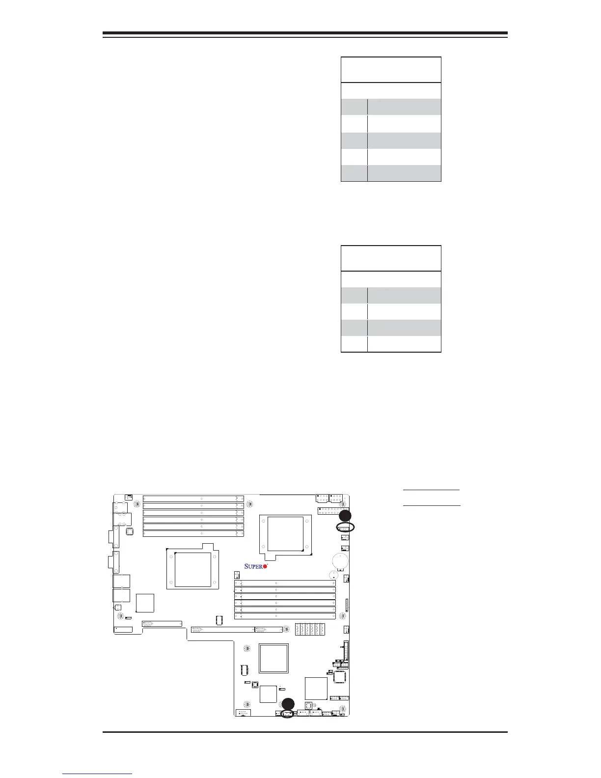
X8DTU/-F
Fan7(CPU2 Fan)
FP CTRL
CPLD
PWRLED/SPK
Rev. 2.01
JPB
JI2C2
JP3
A
B
A. PWR SMB
B. IPMB SMB
IPMB I
2
C SMB (X8DTU-F)
A System Management Bus header
for the IPMI slot is located at IPMB.
Connect the appropriate cable here
to use the IPMB I
2
C connection on
your system.
SMB Header
Pin Defi nitions
Pin# Defi nition
1 Data
2 Ground
3 Clock
4 No Connection
Power SMB (I
2
C) Connector
Power System Management Bus (I
2
C)
Connector (JPI
2
C) monitors power
supply, fan and system temperatures.
See the table on the right for pin
defi nitions.
PWR SMB
Pin Defi nitions
Pin# Defi nition
1 Clock
2 Data
3 PWR Fail
4 Ground
5 +3.3V
 Loading...


