SureCall Force-5 Cellphone-Mate, Inc. Page 10
All rights reserved.
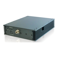
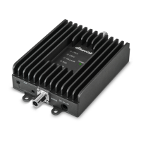
Step 5. Configure Switch Settings
Facing the front of your booster, find 4 banks of dual in-line package (DIP) switches
(see page 5). These switches let you attenuate the dB gain manually for uplink and
downlink channels.
x Bank 1 controls LTE amplification in the building:
o The switches marked LTE 707 control uplink amplification for
Verizon.
o The switches marked LTE-781 control uplink amplification for
AT&T.
o The switches between LTE 707 and LTE-781 control downlink
amplification for both Verizon and AT&T.
x Bank 2 controls Cellular amplification in the building.
x Bank 3 controls PCS amplification in the building.
x Bank 4 controls AWS amplification in the building.
The DIP switches in each bank correspond to the following dB gain values:
For maximum gain on all channels, your booster ships with all DIP switches turned
ON. This setting should always be your starting point when installing or reinstalling
the booster. To change it, move the DIP switches to the ON or OFF position.
x Moving a switch down (away from the LEDs) turns OFF the switch and
increases booster gain for the selected channel.
x Moving a switch up (toward the LEDs) turns ON the switch and
decreases booster gain for the selected channel.