1E-8 Engine Lubrication System:
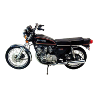
3) Disconnect the oil pressure switch lead wire.
4) Remove the oil pressure switch (1).
Installation
1) Install the oil pressure switch, apply the SUZUKI
BOND to its thread and tighten it to the specified
torque.
: Sealant 99000–31140 (SUZUKI Bond
1207B or equivalent)
Tightening torque
Oil pressure switch (a): 14 N·m (1.4 kgf-m, 10.0
lb-ft)
2) Connect the oil pressure switch lead wire securely.
Refer to “Wiring Harness Routing Diagram in
Section 9A (Page 9A-8)”.
Tightening torque
Oil pressure switch lead wire bolt (b): 1.5 N·m (
0.15 kgf-m, 1.1 lb-ft)
3) Pour engine oil. Refer to “Engine Oil and Filter
Replacement in Section 0B (Page 0B-10)”.
Oil Pressure Switch Inspection
B718H11506009
Refer to “Oil Pressure Indicator Inspection in Section 9C
(Page 9C-9)”.
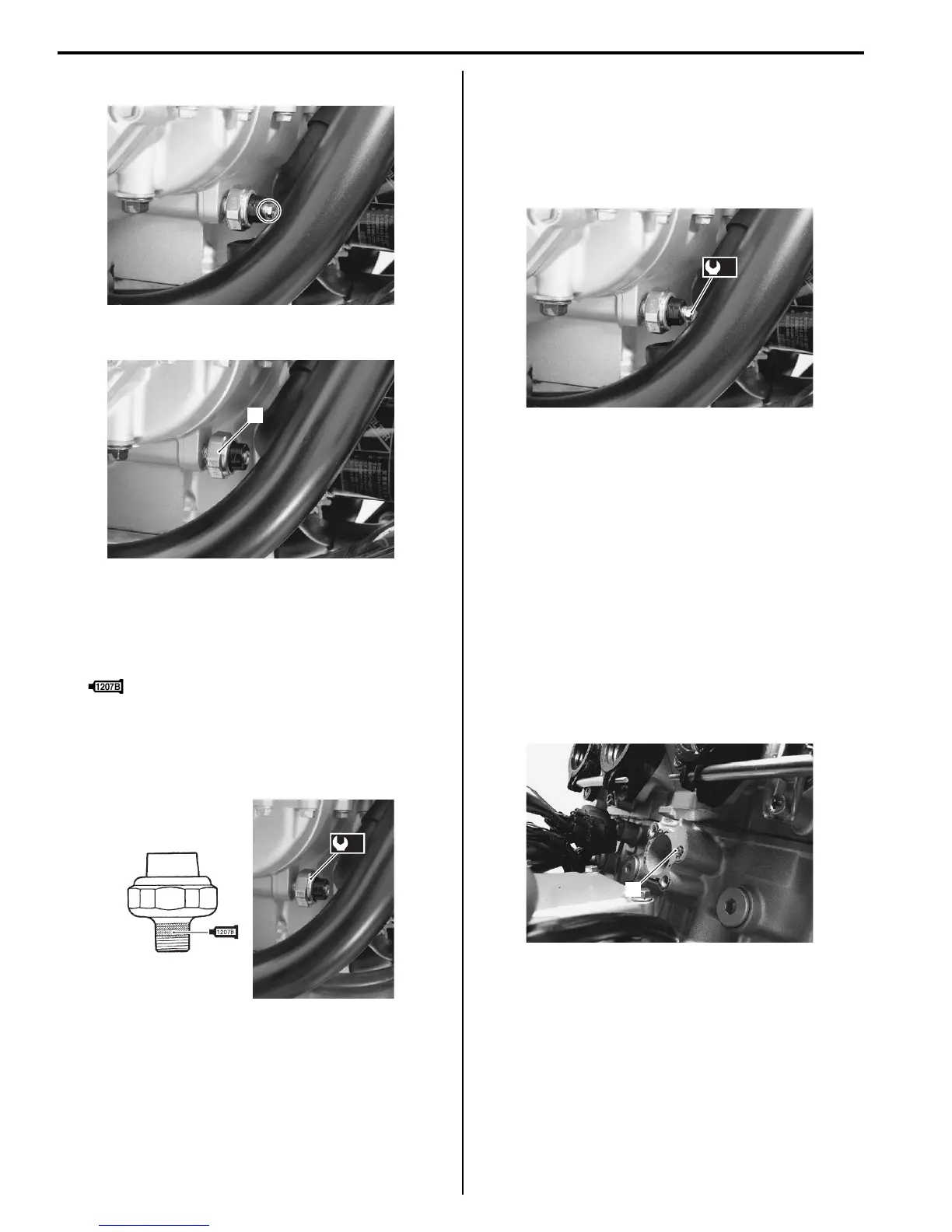
Oil Jet Removal and Installation
B718H11506018
Oil Jet (For Cam Chain Tension Adjuster)
Removal
1) Remove the cam chain tension adjuster. Refer to
“Engine Top Side Disassembly in Section 1D
(Page 1D-24)”.
2) Remove the oil jet (1).
I718H1150039-01
1
I718H1150040-01
(a)
I718H1150041-01
(b)
I718H1150042-01
1
I718H1150043-01
 Loading...