1A-34 Engine General Information and Diagnosis:
Step Action Yes No
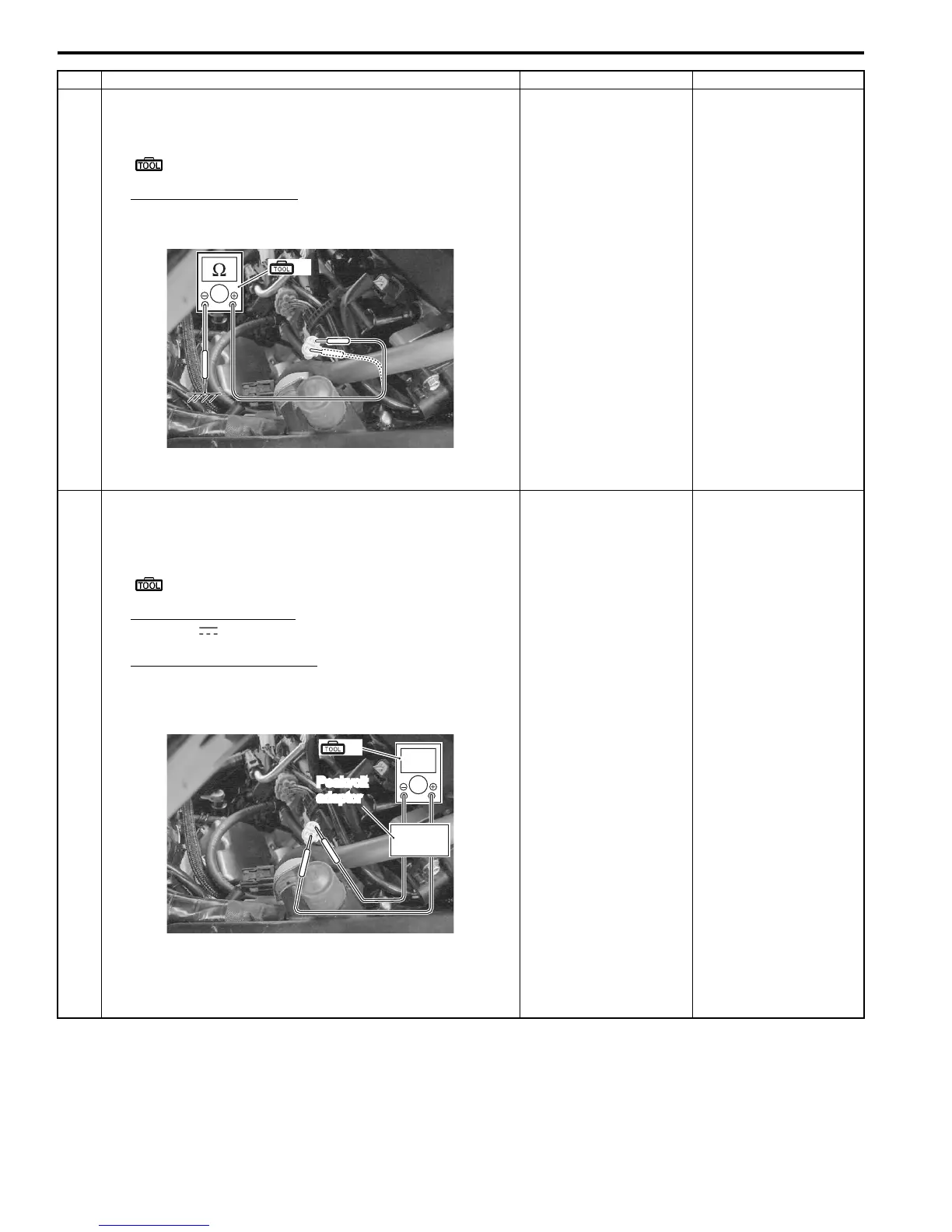
1 5) If OK, then check the continuity between each terminal
and ground.
Special tool
(A): 09900–25008 (Multi circuit tester set)
CKP sensor continuity
∞ Ω (Infinity) (B – Ground, Bl/Y– Ground)
Are the resistance and continuity OK?
Go to Step 2. Replace the CKP
sensor with a new one.
2 1) Crank the engine several seconds with the starter motor,
and measure the CKP sensor peak voltage at the
coupler.
Special tool
(A): 09900–25008 (Multi circuit tester set)
Tester knob indication
Voltage ( )
CKP sensor peak voltage
0.5 V and more
((+) terminal: B – (–) terminal: Bl/Y)
2) Repeat the 1) test procedures several times and
measure the highest peak voltage.
Is the voltage OK?
• B or Bl/Y wire of the
harness side open or
shorted to ground.
• Loose or poor
contacts on the CKP
sensor coupler or
ECM coupler
(Terminal “9” or “21”).
• If the wires and
connection are OK,
intermittent trouble or
faulty ECM.
• Recheck each
terminal and wire
harness for open
circuit and poor
connection.
• Replace the ECM
with a known good
one, and inspect it
again. Refer to “ECM
Removal and
Installation” in
Section 1C
(Page 1C-1).
• Inspect that metal
particles or foreign
material stuck on the
CKP sensor and rotor
tip.
• If there are no metal
particles and foreign
material, then replace
the CKP sensor with
a new one. Refer to
“CKP Sensor
Removal and
Installation” in
Section 1C
(Page 1C-2).
(A)
I947H1110014-01
V
Peakvolt
adaptor
(A)
I947H1110015-01
Manuals by Motomatrix / The Solution For Lost Motorcycle Coded Keys
email: info@motomatrix.co.uk / www.motomatrix.co.uk

 Loading...