SectionII:Installation
2.0.INS.SL-520X
CONTROLS INSTALLATION - AIR SHIFT
1. Attach the valve mount bracket to the
main frame as indicated on Pg. 5-12
with the fasteners provided.
2. Mount the hydraulic control valve
assembly (Pt. No. 23P21) to the valve
mount bracket as shown on Pg. 5-12
with the fasteners provided.
3. Install the hydraulic adapters and
connect the hydraulic hoses (Pt. Nos.
14P38, 14P39 & 14P40) to the control
valve assembly as indicated on Pg. 5-
10.
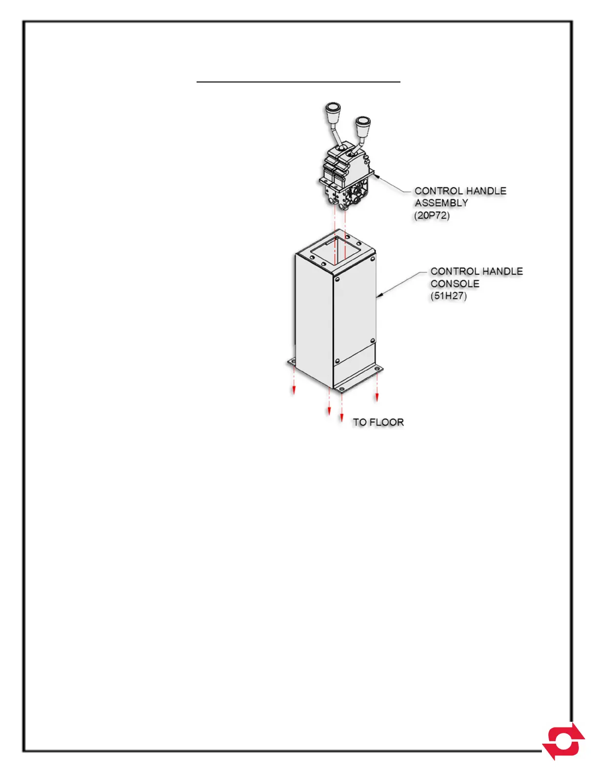
4. Determine the best location in the cab
for the control handle assembly (Pt.
No. 20P72). The location should be
such that the controls can be easily
reached while operating the truck. A
control handle console (Pt. No.
51H27) is provided to facilitate the
mounting of the control handles (see
diagram below).
5. Install the air fittings and hose as
shown on Pg. 5-13 (Air Circuit
Plumbing Diagram). An air pressure
protection valve (Pt. No. 20P74) is
provided so you can tap into the
truck's air supply without jeopardizing the integrity of the air system. The air hose is
provided in a bulk length, which you can cut to length as required for running the air lines.
Take care in routing the air lines and avoid hot areas such as exhaust pipes, etc.