SectionII:Installation
2.0.INS.SL-520X
5. Install the pressure hose as indicated. Tie up the pressure and suction hoses as necessary.
Again, be sure the hoses are routed to avoid exhaust components and to stay clear of the
drive shaft.
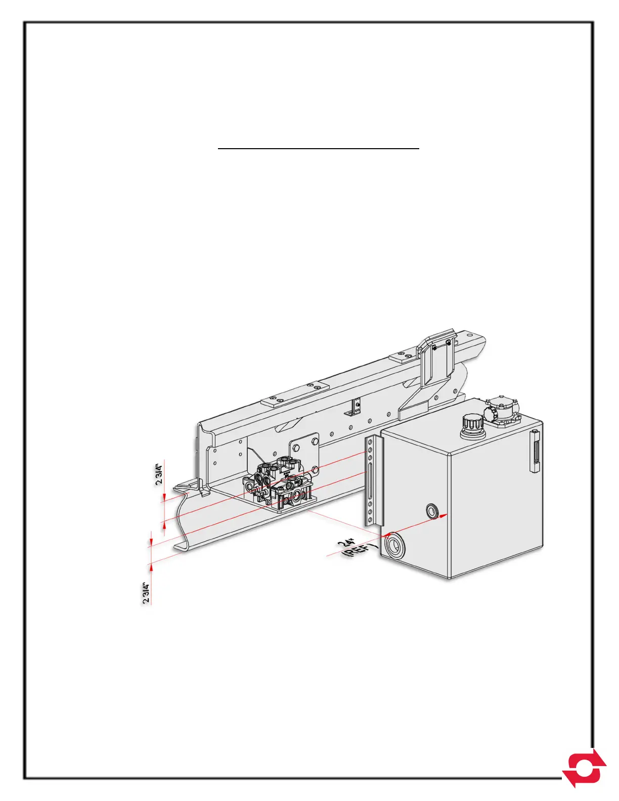
HYDRAULIC TANK INSTALLATION
1. Select a location to mount the hydraulic tank. Reference Fig. G or Pg. 5-10 for the
suggested location of the hydraulic tank to the rear of the control valve assembly on the left-
hand side of the truck. The hydraulic hoses have been sized for the tank to be mounted in
this general area. The tank can be located on the right-hand side or behind the cab, if
necessary, which means longer hoses may be required.
2. Drill four (4) holes for 1/2” diameter bolts (provided) in the mount angle of the hydraulic tank
(two per angle) and the frame rails of the truck chassis. Mount the hydraulic tank and install
the hydraulic filter. Install the hydraulic return hose and the hose barb fitting as shown on
Pg. 5-10. The hose length can be shortened if necessary. Secure the hose to the barb
fittings with the hose clamps provided.
FigureG