2 : 10
Technical Description
Installation Examples
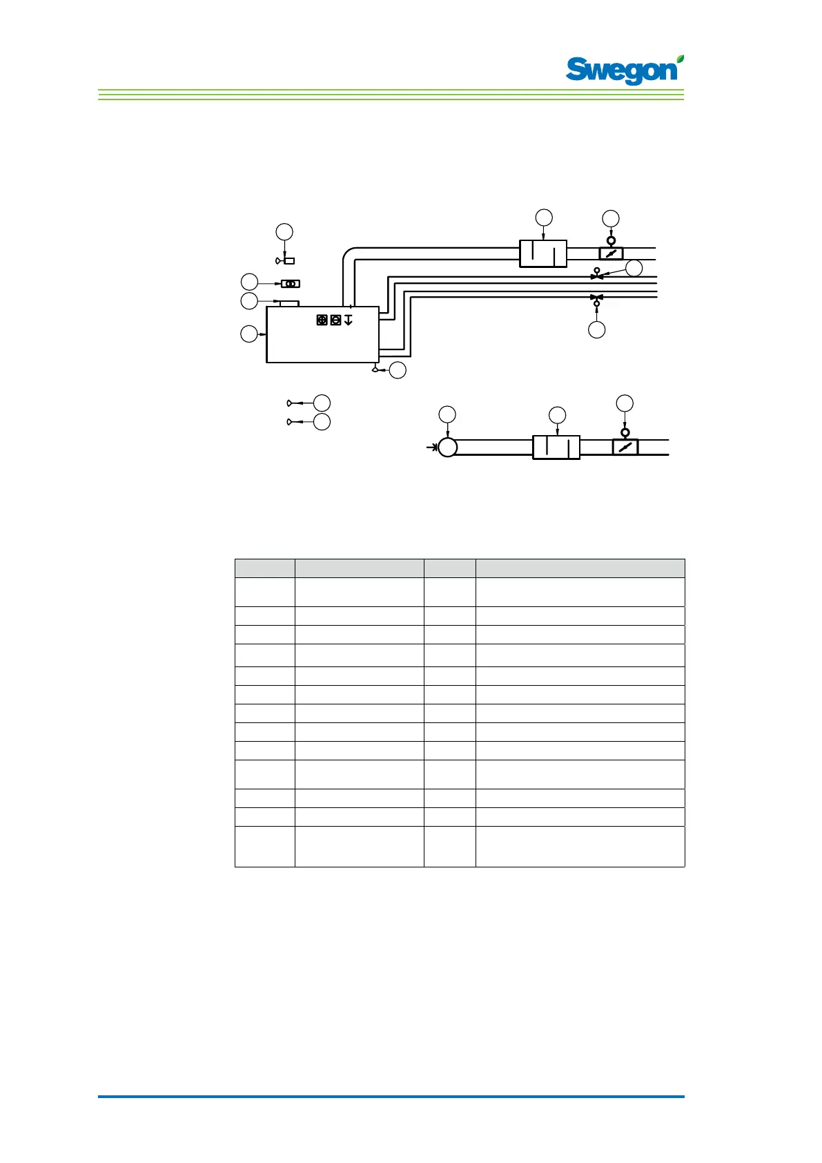
The illustration below shows a typical arrangement of a complete
installation with the CONDUCTOR W1/W3 control system.
5
GT
RU
24V AC
RE
6
4
1
GX
7
GX
GX
9
10
11
2
8
3
12
10
11
Figur 4. Example of a CONDUCTOR W1/W3 installation.
Item Component Quantity Description
1.
PARASOL 1192-B-HF
1
Comfort module including cooling, heating and
ventilation
2.
CONDUCTOR RE W1/W3
1
Controller
3.
CONDUCTOR RU
1
Room unit
4.
SYST TS-1
1
Transformer
5.
SYST CG
1
Condensation sensor
6.
DETECT Occupancy 1 Presence detector
7.
External
1
Window contact, not supplied by Swegon (W3)
8.
LUNA a AT-2
2
Valve actuator
9.
SYST VD 115-CLC
2
Control valve
10.
SYST CRTc 9-125-2 CM 24
1
Supply air damper 1 including motor (W3)
Extract air damper 1 including motor (W3)
11.
CLA 125-500
1
Sound attenuator
12.
Extract air register
1
Extract air register with given C-Factor
Accessories
SYST MS
4
Assembly part for suspending the PARASOL
Not necessary if the product is mounted directly
against the ceiling.