5 : 41
Service
Service
This section is intended only for use by personnel who are specially trained
by Swegon.
Parameters
In order to control the functions in the CONDUCTOR W1/W3, there are
a number of parameters, which can be changed in order to optimize the
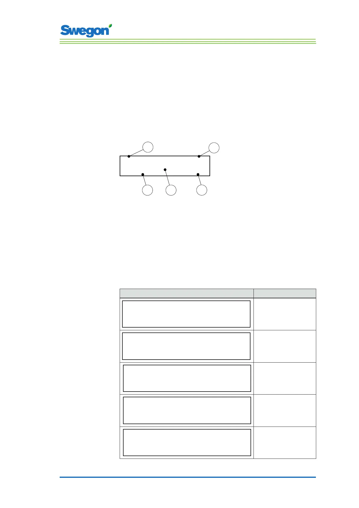
current installation. In the display of the room unit (thermostat) every
parameter is shown in accordance with the figure below.
P_xxx
xxxxxx
xxxxxx
Min xx
Max xx
1
4
5
2
3
Figur 1. Main image in the display of the room unit
Pos 1. Minimal value.
Pos 2. Parameter number.
Pos 3. Factory-preset value
Pos 4. Maximum value.
Pos 5. Parameter text.
System parameters
System parameters are basic parameters which are common for several
applications.
Display image Description
P_101 set 2 ID
Modbus Address
min 1 max 247
Indicates the ModBus address.
P_102 set 3
BMS Baudrate, 9.6 19.2 38.4
min 1 max 3
Indicates the transmission speed
for connecting up to a Building
Management System (BMS).
1 = 9.6
2 = 19.2
3 = 38.4
P_103 set 2
BMS Parity 0=Od. 1=Ev. 2=None
min 0 max 2
Parity setting for connection
to BMS.
0 = Uneven
1 = Even
2 = None
P_104 1
BMS Stop bits
min 1 max 2
Number of stop bits for
connection to BMS.
1 = 1 bit
2 = 2 bits
P_105 3
Component type, 2=DC, 3=RC
min 2 max 3
Indicates the current type of
controller.