GB.SILVERSK.170901
We reserve the right to alter specifications.
www.swegon.com 29
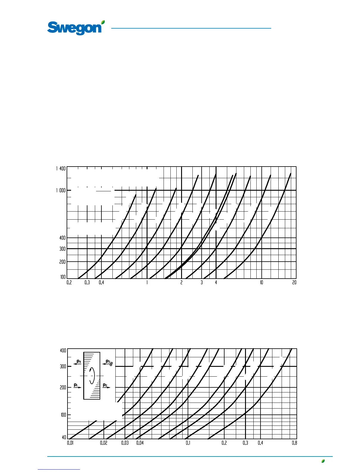
5.2 Auxiliary diagram for measuring airflows
SILVER C
04, 05, 07
08, 11
12, 14
20, 25
30, 35
60, 70
80, 100
50
120
40
The pressure reading on the manometer corresponds to
the airflow according to the diagram below.
Airflow, m
3
/s
Pressure, Pa
Leakage and purging air flow, m
3
/s
Differential pressure P
1
- P
3
, Pa
Applicable to temperature t=20°C.
For other temperatures, correct the pressure
reading using the following formula:
P
corr
= P
read
x
273 + t
293
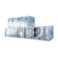
Correction diagram
for rotary heat exchangers
If a rotary heat exchanger is located between the fan that
has generated the airflow according to the above, and the
point at which it is desirable to calculate the airflow, then
the flow must be corrected according to diagram below.
The leakage and purging airflow go from higher to lower
pressure. The pressure on the supply air side is normally
higher, which means that the outdoor airflow is the supply
air fan's airflow plus the leakage and purging airflow, and
the extract airflow is the extract air fan's airflow minus the
leakage and purging airflow.
04, 05
07, 08
11, 12
14, 20
25, 30
35, 40
50, 60
70, 80
100, 120
Applicable on condition that
the pressure balance inside
the unit has been correctly
adjusted.
5.1 To connect manometers
If a U-tube manometer or a Magnehelic manometer has
been supplied by Swegon, see separate instructions.
If no manometer has been supplied by Swegon:
The hoses supplied (blue (-) and white (+) lying inside
the fan space) are, from the factory, connected to the
measurement points of the fan. The installation of nipples
(measurement tappings) on the inspection door of the air
handling unit and the further running of hoses to a ma-
nometer must be done at site (not Swegon).
5. Measurement of the airflow
For rotary heat exchangers, the airflow should also be cor-
rected according to the correction diagram.