4. Fuel Injection System
4-21
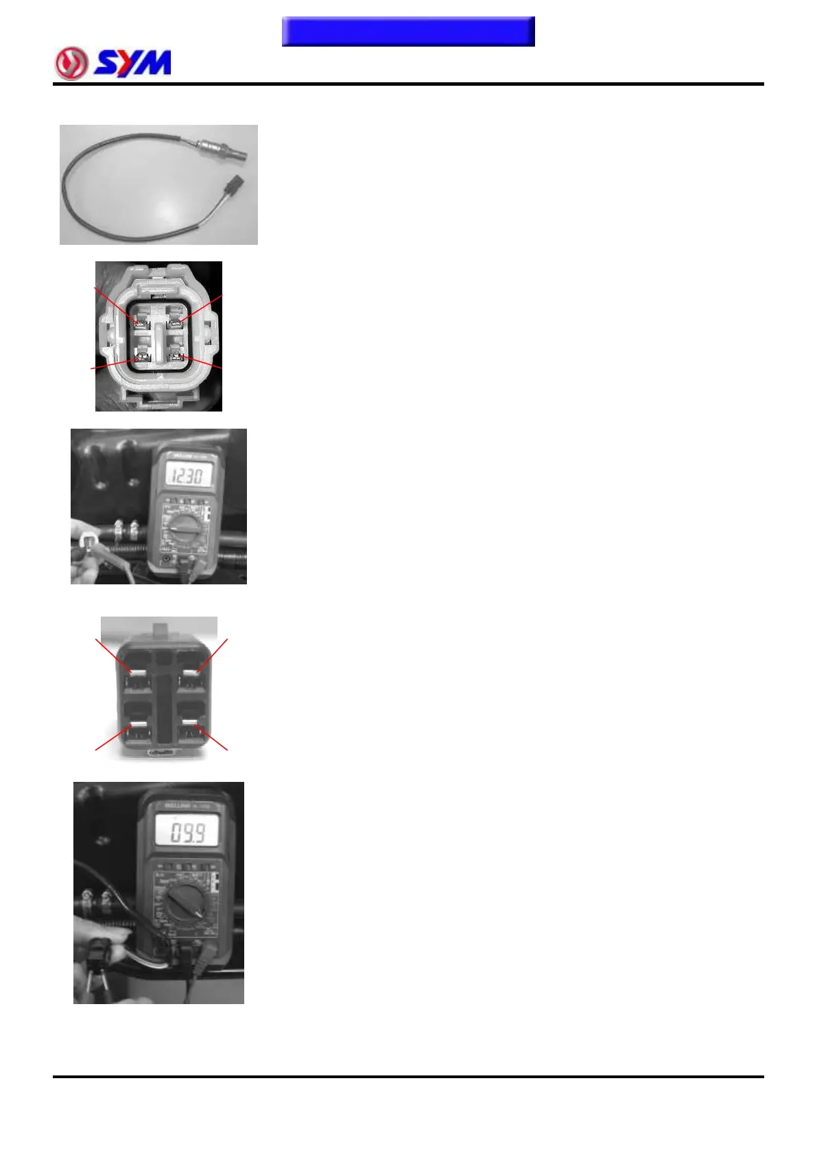
O2 Sensor
Confirmed working voltage
Resistance Confirmation
Functional Description:
● Use 8 ~ 16V DC power supply, has the 4-pin coupler, a power supply
pins for heater; for a heater control pin; signal for a grounding pin; O
2
for a signal pin.
● O
2
Sensor output feedback signal to the ECU fuel ratio control in the
vicinity of 14.5 ~ 14.7, a closed-loop fuel control.
● When the air-fuel ratio control in the near equivalent, CO / HC / Nox to
have the highest conversion efficiency.
Testing Procedures:
1. Voltage confirmed:
● Removed O
2
Sensor and the wire harness between the coupler.
● Open the main switch, but not to start engine.
● Use "voltage meter" DC stalls (DCV) to check inlet pressure sensor
voltage.
● Confirmed working voltage:
Voltage meter negative access to the wire harness sensor coupler
2nd pin (Red / Orange).
Voltage meter positive access to the wire harness sensor coupler
first pin (Red / Yellow).
2. Resistance Confirmation:
● Remove O
2
Sensor and the wire harness between the coupler.
● Use of the "meter" Ohm stalls, Measurement O
2
Sensor heater
resistance.
● Measurement resistance value
Ohm meter negative access to the O
2
sensor coupler 2nd pin
(White).
Ohm meter negative access to the O
2
sensor coupler first pin
(White).
 Loading...