Chapter 2 Features and Functions
In Case of a Problem
Getting Started Guide 2-25
NOTE Remove the Tee connector and restore antenna connection as loading of
the Tee connector will prevent proper reception of the GPS signal by
the antenna.
Figure 2-8. Measuring +5 Volts Across Antenna Input
Symptom
Same as previous symptoms, except Receiver Position Mode = Hold.
Solution
Enable SURVEY mode using specified command.
Receiver not maintaining GPS lock
Symptom
Position data incorrect.
Solution
Survey to obtain correct position,
or
Correct position data using specified command.
Symptom
Position data correct.
Sufficient satellites in view.
No satellites tracked.
Solution
If candidate satellites are marked “Ignore” on status screen, disable
the feature which ignores satellites.
If candidate satellites are below the mask angle specified on the
Receiver Status screen, lower the elevation mask angle using the
proper command. Default is 10 degrees—all satellites between the
horizon and 10 degrees of the horizon are masked.
1 Tee-connector 2 DVM
11
22
33
44
55
66
77
88
99
PC
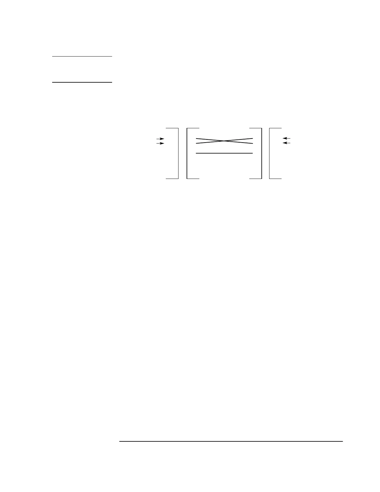
RS-232C (9-pin)
RX
TX
PC input
PC output
GND
DE-9P
Male
59551A PORT 2
RS-232C (9-pin)
DE-9S
Female
DE-9S-to-DE-9P
(DTE-to-DCE) Interface Cable
Data
Terminal
Equipment
Data
Communications
Equipment
DE-9S
Female
DE-9P
Male
RX
TX
GND
Instrument input
Instrument output
 Loading...