SS-300-000 8 I56-2967-000R
©
2007 System Sensor
Three-Year Limited Warranty
System Sensor warrants its enclosed product to be free from defects in materials and workman-
ship under normal use and service for a period of three years from date of manufacture. System
Sensor makes no other express warranty for the enclosed product. No agent, representative,
dealer, or employee of the Company has the authority to increase or alter the obligations or
limitations of this Warranty. The Company’s obligation of this Warranty shall be limited to the
replacement of any part of the product which is found to be defective in materials or workman-
ship under normal use and service during the three year period commencing with the date of
manufacture. After phoning System Sensor’s toll free number 800-SENSOR2 (736-7672) for a
Return Authorization number, send defective units postage prepaid to: System Sensor, Returns
Department, RA #__________, 3825 Ohio Avenue, St. Charles, IL 60174. Please include a note
describing the malfunction and suspected cause of failure. The Company shall not be obligated
to replace units which are found to be defective because of damage, unreasonable use, modi-
fications, or alterations occurring after the date of manufacture. In no case shall the Company
be liable for any consequential or incidental damages for breach of this or any other Warranty,
expressed or implied whatsoever, even if the loss or damage is caused by the Company’s negli-
gence or fault. Some states do not allow the exclusion or limitation of incidental or consequen-
tial damages, so the above limitation or exclusion may not apply to you. This Warranty gives
you specific legal rights, and you may also have other rights which vary from state to state.
Please refer to insert for the Limitations of Fire Alarm Systems
H0558-00
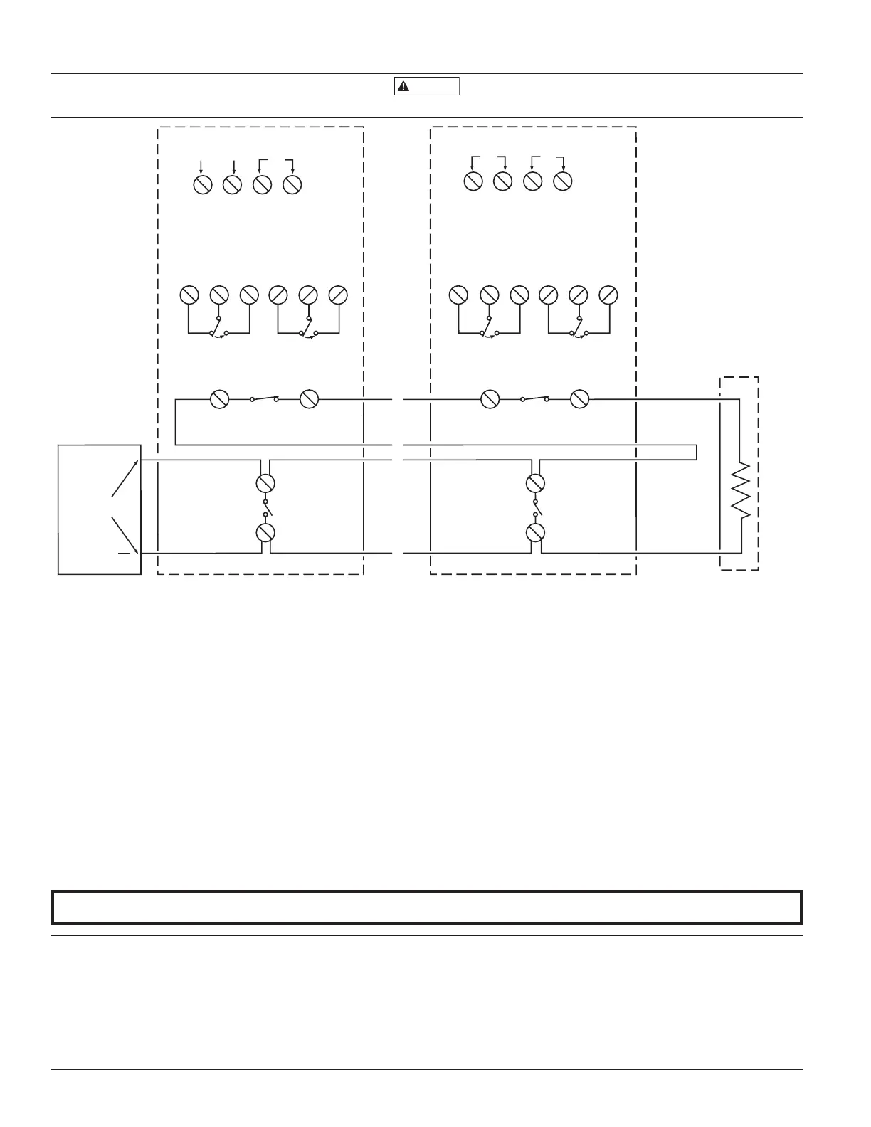
Figure 14. System wiring diagram for 4-wire duct smoke detectors:
24VAC/DC
9 10
POWER INPUTS (NOTE 1)
AUXILIARY CONTACTS
FOR FAN SHUTDOWN, ETC. (NOTE 2)
16
617
8 18 7
N.O.
C.
N.C.
N.O.
C.
N.C.
16
617
8 18 7
N.O.
C.
N.C.
N.O.
C.
N.C.
SUPERVISORY TROUBLE CONTACTS (NOTE 3)
24V
910
POWER INPUTS (NOTE 1)
AUXILIARY CONTACTS
FOR FAN SHUTDOWN, ETC. (NOTE 2)
SUPERVISORY TROUBLE CONTACTS (NOTE 3)
SUP C. SUP N.O.
SUP N.O.
SUP C.
5
4
ALARM
INITIATION
CONTACTS
(NOTE 4)
5
4
ALARM
INITIATION
CONTACTS
(NOTE 4)
ALARM
INITIATION
LOOP
UL LISTED 4-WIRE
CONTROL PANEL
FIRST DETECTOR IN THE LOOP LAST DETECTOR IN THE LOOP
EOL RESISTOR
SPECIFIED BY
PANEL MANUFACTURER
+
120
VAC
120
VAC
OR
OR
AUX A
AUX B
AUX A
AUX B
ALARM C.ALARM C.
ALARM N.O.
ALARM N.O.
~
~
~
~
~
~
~
~
14
14
3
3
Do not loop wire under terminals when wiring detectors. Break wire runs to provide system supervision of connections.
NOTE 1: 24V Power Inputs accept a non-polarized 24VDC or 24VAC 50-
60Hz. 120VAC Power Inputs accept only 120VAC 50-60Hz. Connect power
source to appropriate terminals of each detector. See specifications for ad-
ditional power supply information.
NOTE 2: Auxiliary contacts shown in standby position. Contacts switch
during alarm as indicated by arrows. Contacts will also switch during
sensor maintenance, loss of communication with sensor, and when cover
tamper times out if Shutdown on Trouble feature is selected. Auxiliary
contacts are not to be used for connection to the control panel. See speci-
fications for contact ratings.
NOTE 3: Trouble contacts shown in standby position. Open contacts indi-
cate a trouble condition to the panel. Contacts open during sensor main-
tenance, loss of communication with sensor, loss of power, or when cover
tamper feature times out. See specifications for contact ratings.
NOTE 4: Alarm Initiation contacts shown in standby position. Closed con-
tacts indicate an alarm condition to the panel. Contacts close only during
an alarm condition. See specifications for contact ratings.