D200-100-01 2 I56-3888-010
Designing detailed pipe networks using PipeIQ™ is beyond the scope
of this manual. For advice on a design approach, see Appendix F.
USING PipeIQ™ TO CONTROL OR MONITOR FAAST LT-200
FAAST LT-200 USB Connection
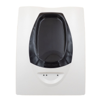
PC connectivity is provided by an on board USB B socket located
in the middle of the FAAST LT-200 unit behind the hinged front
cover. The USB interface allows access to a range of additional
options via PipeIQ™.
Note: To connect, access or change any FAAST LT-200
conguration parameters, the device must be in Maintenance
mode (See Password Procedure to enter Maintenance mode).
Connecting a PC to a FAAST LT-200 Device for the First Time
Minimum System Requirements
Microsoft Windows Vista, 7, 8 or 10, XP - SP3 (not recommended).
1 GB of RAM.
Graphics hardware with 128 MB of memory and support for
OpenGL 2.0 or later.
5 GB of free hard disc space
Power-On/Initialisation
A FAAST LT-200 device always powers on in the Initialisation state
where internal checks are completed and the air ow/fan speed is set
before entering the Normal state.
Normal
In the Normal state the FAAST LT-200 operates as a smoke
detector. The main button actions are not active, apart from the
combination Reset + Disable which shows the fan speed number,
and the Reset button itself providing access to the Password
Procedure to go to the Maintenance state.
Note: For the loop based FAAST LT-200 device, the module
address will only respond to a panel poll when in Normal mode.
Maintenance
When the correct password is entered, a FAAST LT-200 device will
enter the Maintenance state (See Password Procedure for more
information). The front panel buttons are enabled for maintenance
functions and the FAAST LT-200 unit can be linked to a PC. (See
Remote Maintenance state).
A FAAST LT-200 device will automatically time-out of the
Maintenance state after a preset period of inactivity (Default is 5
minutes).
Remote Maintenance
The USB connection can only be used when the FAAST LT-200
device is in the Remote Maintenance mode. To enter the Remote
Maintenance mode, rst put the device into Maintenance mode,
open the hinged front cover and connect to a PC with a USB cable
(within 5 minutes). In Remote Maintenance mode it is possible to
control, monitor and re-programme the FAAST LT-200 device via the
PC using PipeIQ™ (Version 2.9.1 and above).
The Remote Maintenance mode does not have a time-out. The
FAAST LT-200 device will return to Maintenance mode when the
USB cable is unplugged and the door is rmly shut. (Note: if the door
is not shut within 5 minutes of removing the USB cable, the unit will
enter Service mode.).
Service Mode
When the FAAST LT-200 device is in Normal, the Service Mode
state is entered automatically when the front cover is opened.
The FAAST LT-200 unit switches o the power to the unit. Once
the service action is complete, and the front cover is closed, the
FAAST LT-200 device restarts automatically. Note that when
leaving Service Mode, a unit will always run the initialise routine,
re-calibrating the air ow settings.
Power Out Of Range State
If the PSU voltage is out-of-range, the FAAST LT-200 unit will stop
working, switching o the power to the unit and signalling a power
fault and a general fault.
The FAAST LT-200 device remains in this state until it is re-powered
or restarts automatically when the supply voltage returns to within
the correct range.
PASSWORD PROCEDURE (To enter Maintenance Mode)
Press and hold RESET; left hand ow indicator will turn yellow
then green.
Release RESET and FAULT indicator will switch on green. The left
hand ow indicator will blink green indicating the device is ready
for the rst digit.
Press DISABLE to increment the LEDs 1…9; press TEST (tick
button) to select a digit.
The ashing airow segment will turn solid green and the next
segment will begin to ash indicating set the next digit. When the
4th digit is selected, all 4 airow segments are turned o. If the
password is accepted the FAULT indicator will remain green and
the unit enters Maintenance mode. If the password is incorrect
the FAULT indicator ashes yellow and the unit remains in Normal
mode. The Default password in 3111.
If no button is pressed for 10s during the password sequence, the
unit returns to Normal mode. If there is no activity in Maintenance
mode for 5 minutes (default), the fault indicator blinks green for 15s
and then the unit returns to the Normal state.
When the USB cable is plugged into the unit, it switches to Remote
Maintenance mode; the maintenance time-out is disabled.
AN INTRODUCTION TO PIPEIQ™
Overview
The PipeIQ™ software program (version 2.9.1 or higher) is a
convenient and powerful Windows
®
based application that can
be used to set-up and monitor the performance of FAAST LT-200
Aspiration devices via a graphical user interface on a PC.
PipeIQ™ also provides facilities to develop and verify the
performance of pipe network solutions, congure the design
parameters to suit local re codes and standards and generate
pipe layout diagrams, BoMs, parameter tables and event log
reports.
With a detailed Help Menu to guide the user through the dierent
screens and options, PipeIQ™ is a comprehensive package
to support the use of the FAAST LT-200 detector in aspirating
applications.
Information on downloading and installing the latest versions of
PipeIQ™ can be found in Appendix E of this manual.
The PipeIQ™ User Interface
The graphical user interface for PipeIQ™ includes a title bar, menu
bar, toolbar, left pane, right pane, and status bar as described in
the following table:
Menu bar
Contains six menus that perform various
tasks such as open, close, save, change
the view, etc
Toolbar
Contains buttons to create, open or save
projects
Left pane
Displays all the project elements in a tree
structure
Right pane
Displays detailed information of the item
selected in the left pane
Status Bar
Displays the type of operation (on tabs at the
bottom of the Left Pane)
Tabs: Configuration; Pipe Design; Monitoring