D200-100-01 21 I56-3888-010
APPENDIX F
PipeIQ™ AND PIPE SYSTEM DESIGN
PipeIQ is a design application to help a user create EN54 compliant
pipe layouts. Generating a suitable working design will require
some thought and understanding of the interacting variables in an
aspirating system.
The following methodology can assist when trying to design a
pipe network using PipeIQ. By following this sequence of steps,
it should be possible to arrive at an acceptable design (assuming
one exists) that has adequate air ow and hole sensitivity to
operate within the overall limits of the aspirating device. (See Pipe
Design Methodology Flow Chart.)
Suggested Design Methodology
1. Start a project in PipeIQ, choose the detector type, select the
aspirating class and follow the instructions to add a detector
and create a representation of the physical pipe layout.
To optimise the design:
2. In the Manage Pipe – Edit Properties window, set the number
of sample holes and hole spacing in the pipe network to comply
with local re regulations and the EN54 approved gures. The
hole diameters can also be set in this window, or changed later.
To end, click Update Holes and then OK.
3. In the Design tab, click on the Calculations button; the
Calculation window will appear. Set the sample hole diameters
and fan speed to get the ow in the detector close to 45l/min.
4. Repeat step (3) above to eliminate any red boxes (out-of-range
sensitivity, transport time etc.)
5. Check the ow balance is ≥0.5. Using the auto-balance button
will probably create multiple sample hole diameters along the
pipe; avoid using this button if a single hole size is required. Be
aware that the auto-balance function may also reduce the
pipe air ow, ensure this is set back close to 45l/min.
6. Repeat from step (3), adjust hole diameters and fan speed to
achieve all the above gures.
7. Next, check that the sample hole sensitivity is practical for the
chosen class, i.e. it is not too sensitive. Ideally, to avoid false
alarms, hole sensitivity for a class C system should be 1%/m or
greater and certainly >0.5%/m.
8. If necessary, change the Alarm level to reduce the sample hole
sensitivity. The detector sensitivity is set from the Conguration
tab.
9. Repeat from step (3) to nalise the pipe design and save.
Tips to achieve an adequate design
Maintain the air ow in a FAAST LT unit at, or around, its optimum
setting of 45 l/min. Increase/decrease hole diameters and fan
speed to achieve this.
Fewer holes in a pipe will tend to increase the sample hole
sensitivity. Adding extra holes close together may mathematically
appear to reduce the hole sensitivity, but in practical terms the
system sensitivity will remain high. Change the alarm level to raise
or lower the sensitivity of the sample holes.
Changing the hole diameter will aect the hole sensitivity and the
hole balance. Smaller holes may improve the balance but will
reduce the overall ow. Ensure this remains as close to 45l/min as
possible. It is recommended that the ow balance is not less than
0.5 for an acceptable design.
Longer pipes will obviously have longer transport times; they also
tend to reduce the air ow, which further extends the transport
time. Rather than using one long single pipe, the use of a ‘T’ tap
or two pipes per channel can reduce long pipe runs and reduce
the transport time. It also helps with maintaining the air ow speed
at the optimal level, since it is equivalent to increasing the pipe
diameter to the aspirating device; but beware the ow does not
get too high. In twin pipe systems it may be necessary to reduce
hole sizes, compared with a single pipe, to achieve optimal ow.
Alternatively, the fan speed can also be reduced, but both these
actions will increase the transport time.
Use of the Auto-balance button in PipeIQ will probably give the
holes in the pipe design a variety of dierent diameters. If one
size of hole in the sample pipe is desirable (for simpler installation
and commissioning) do not use this button. Pipes with equal size
sample holes are also easier to test – the farthest end sample hole
will be the least sensitive.
Note that the fan speed setting is required to calculate the reference
air ow in PipeIQ. However, a FAAST LT device will automatically
set the correct air ow at commissioning time, when used in the
normal auto fan mode (set as default). It is not necessary to set
the fan manually.
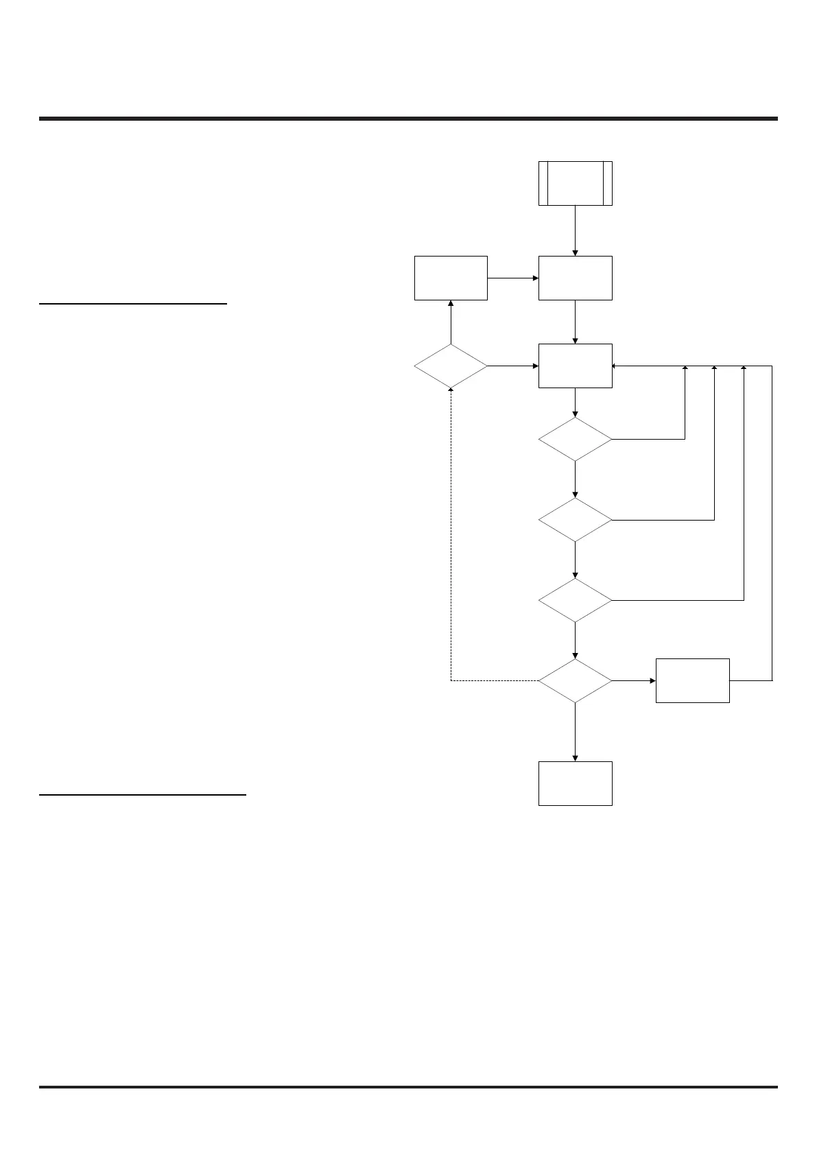
Pipe Design Methodology Flow Chart
Set number of
holes and hole
spacing
Start Project
and create
pipe layout
Set sample hole
diameters and fan
speed
Is air flow
c.45l/min?
Are the
parameters in
range?
Is the flow
balance ≥ 0.5?
Is hole
sensitivity OK
for class?
Change alarm
level
Save design
Y
N
Y
N
Y
Y
N
N
Review pipe
layout
Is a design
possible?
N
Y
??
PIPE DESIGN METHODOLOGY FLOW CHART