29
Rev. 12GB0712
SYSTEMA S.p.A.
AIRTIGHT GAS CONVECTORS
5) Re-close the cast-iron front panel, making sure that
the fiberglass sealing liner remains in place.
6) Check for leakage of gas along the threaded joints.
7) With a 20 mbar supply pressure read on the pres-
sure tap (2), use the adjustment screw (3) to bring
the pressure of the burner (1) to its nominal rating
plate value. Screwing in the clockwise direction
3.6 Adaptation of the electronic
devises for France and
Belgium (Mod. K21E, K28E,
K40E, K55E, K28VE, K40VE,
K55VE, K21FE, K28FE, K40FE,
K55FE)
The transformation must be performed exclusively by
qualified professional personnel in complete respect of
the safety rules in force; the manufacturer declines liabi-
lity for damages caused by the erroneous transformation
or incorrect and/or inappropriate use of the device.
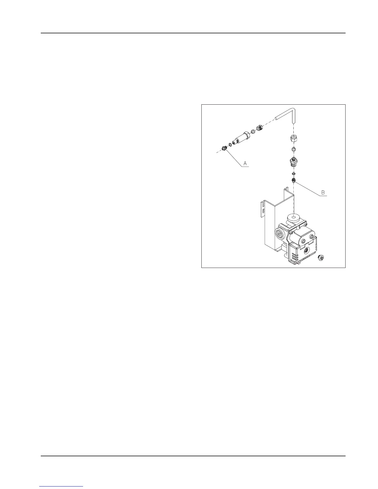
For France and Belgium, in case of methane gas fee-
ding, the valve must be installed us the one represented
on the draw.
For the transformation from LPG into METHANE gas,
the burner nozzle must be substituted (A see draw 31)
and remove the diaphragm (B see draw 31).
3.7 Electrical connections from
the control panels to the devi-
ces
Check to make sure that a good ground connection has
been made and respect the correct connections of the
phase and neutral wires. otherwise the flame detection
and control systems will not work.
increases the pressure, while unscrewing counter-
clockwise decreases the pressure.
8) Indicate on the rating plate the type of gas transfor-
mation performed on the device.
Draw 31