6
Rev. 12GB0712
SYSTEMA S.p.A.
AIRTIGHT GAS CONVECTORS
CONVECTOR FLUE GAS-AIR KIT
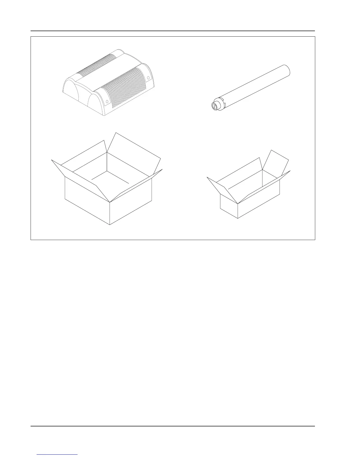
Draw 1 Package contents
2.3 Description and operational
characteristics
The airtight gas convector radiator is composed of a
combustion chamber for the combustion of a gaseous
component (methane or LPG) in airtight cast iron divi-
ded into two half-shells that can be opened for cleaning
and the inspection of the burner. The working tempera-
ture of the external surface of the combustion chamber
as fanned by the natural convection movement of the
surrounding air or the forced circulation of the fans is
usually reached in a few minutes.
The device functions automatically, and is equipped with
the appropriate systems for safety, control, mixing, com-
bustion, starting, the suction of combustion air and flue
gas expulsion.
The combustion air suction and flue gas expulsion
systems must be mandatorily connected directly to the
building’s exterior (C-type devices) and therefore there
is no contact between the combustion chamber and the
building’s interior. This guarantees the maximum safety
and permits the installation of the device indoors in com-
plete respect of the standards in force.
2.4 Principal elements of the con-
trol and safety systems
a) Electric control unit for the Electronic series
models: this can be of two types depending on the
convector model involved (forced or naturally
balanced circulation). After receiving the electric
signal from the room thermostat, the control unit
runs a normal check on the pressure-switch when
forced convectors are being controlled (if this check
is not positive, the control unit does not grant trig-
gering). The control unit then gives the signal for
the performance of the pre-starting lubrication of
the combustion chamber (>4 lubrications) and then
the signal for spark ignition and starting by opening
the gas solenoid valve. If no flame is detected (by
the ionization probe) within the established safety
time, the device goes into lock-out. In order to reset
after lock-out, switch off the bipolar switch with the
orange l.e.d. and then switch it back on again.