26
Rev. 12GB0712
SYSTEMA S.p.A.
AIRTIGHT GAS CONVECTORS
3.3 Gas line connection
The gas line connection must be made with respect to
the regulations in force.
a) The device cannot withstand pressures of higher
than 40 mbar (0,04 bar) without risking the breaka-
ge of the gas valve membrane.
b) Always use ball valves and flexible joints for gas
when connecting the devices.
c) Gas supply line pressure adjustment: all the devices
are tested and calibrated at the Manufacturer’s fac-
tory for their respective operating pressures (see the
data provided in the table).
To check the outlet pressure (Natural gas) use the check
point 4 (Draw 30) and 1 (Draw 30a) placed above the
valve outlet after removing the locking screw. In case the
pressure value should not corrispond to the valued indi-
cated check (burner working) the inlet pressure trough
the check point (5 Draw 30) the inlet pressure must be
like indicated in the tables to the page 8, 9.
For gas LPG (butane-propane), the valve flow adjuster
must be totally excluded. On the heaters supplied with
EUROSIT valve turn anti-clock-wise 1/2 spin the pressu-
re adjuster 9 (Draw 30). On the heaters supplied with
WHITE ROGER or SIT 850 MICRO turn completely the
pressure adjuster 3 as Draw 30a. To check the inlet pres-
sure use the check point placed (5 Draw 30 and 2 Draw
30a) above the valve inlet gas connector. Whenever the
inlet pressure values should not correspond to the value
indicated on the regulation data table, adjust the pressu-
re (burner working) manually trough the pressure adju-
ster placed on the top of the valve.
After these pressure adjustment operations have been
completed, remember to close the pressure taps located
on the gas safety valve using the respective screws.
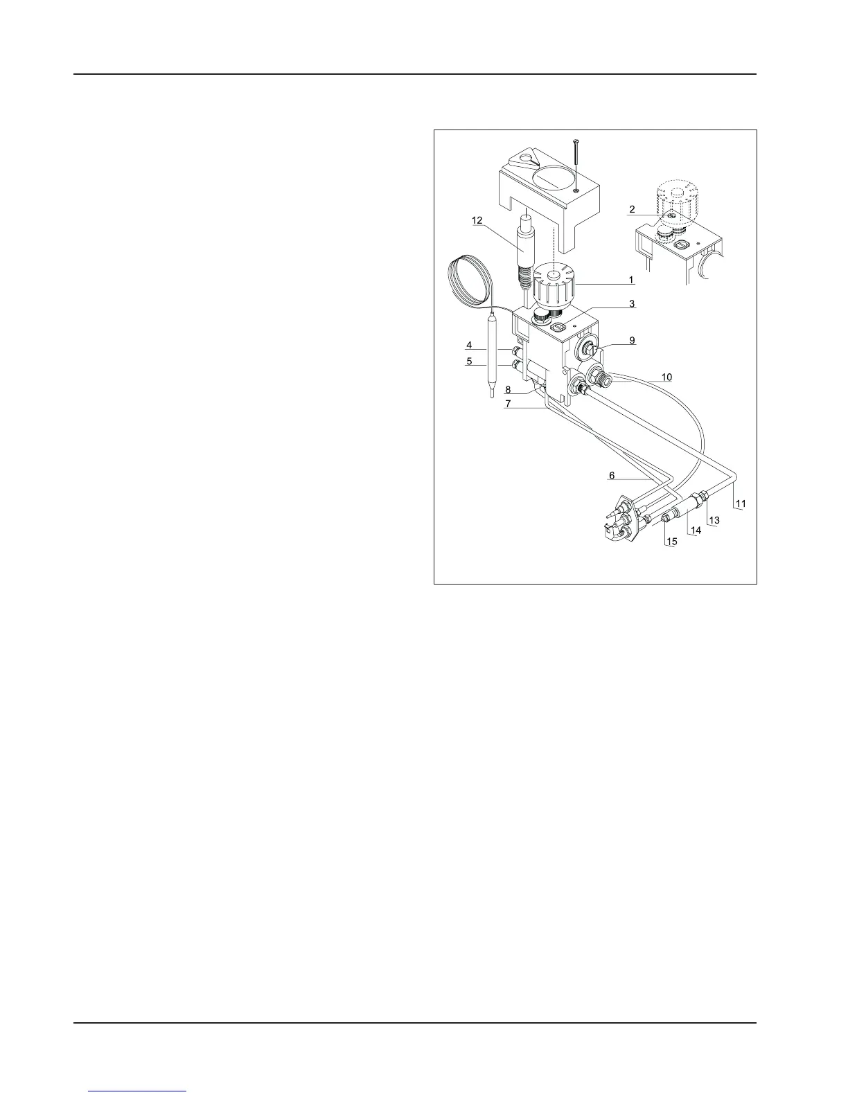
VALVE FOR PILOT FLAME DEVICES (K21, K28, K40,
K55, K28V, K40V, K55V)
LEGEND
1) Control dial
2) Pilot frame adjustment screw
3) Minimum flow adjustment screw
4) Outlet pressure tap (at nozzle)
5) Inlet pressure tap (from mains)
6) Pilot flame supply line pipe
7) Thermocouple
8) Magnet unit
9) Pressure regulator - stabilizer
10) Gas inlet connector thread
11) Main burner supply line pipe
12) Piezoelectric button
13) Sealing connector
14) Nozzle-holder sleeve
15) Nozzler
“EUROSIT” TYPE
Draw 30