7
Rev. 12GB0712
SYSTEMA S.p.A.
AIRTIGHT GAS CONVECTORS
CONTROL UNIT TECHNICAL CHARACTERISTICS
Power supply voltage . . . . . . . . . . . . . . . . . . . . . . . . . . . . . . . . . . . . . . . . . . . .220/240 V 50/60Hz
Work temperature . . . . . . . . . . . . . . . . . . . . . . . . . . . . . . . . . . . . . . . . . . . . . .-20 ÷ 60°C
Pre-starting lubrication time . . . . . . . . . . . . . . . . . . . . . . . . . . . . . . . . . . . . . . .10 s
Starting safety time . . . . . . . . . . . . . . . . . . . . . . . . . . . . . . . . . . . . . . . . . . . . .max. 5 s
Switch-off safety time . . . . . . . . . . . . . . . . . . . . . . . . . . . . . . . . . . . . . . . . . . . .< 1 s
b) Pilot gas valve: there is only one type of pilot gas
valve for all pilot flame convector models - a multi-
functional valve with single control and combined
manual all-or-nothing thermostat control equipped
with thermoelectric flame detection device with
reset inhibition, maximum flowrate pre-selection
device or pressure regulator, minimum flowrate pre-
selection screw, all-or-nothing modulation thermo-
stat, pilot flame output with gas flowrate pre-selec-
tion screw, inlet filter and pilot filter, inlet and outlet
pressure taps - lateral gas outlets or gas outlets
from below with RP 3/8 ISO 7 threads. To start,
press the dial and switch on the pilot flame by kee-
ping the dial pressed down for a few seconds. Then
release the dial and check to make sure that the
pilot flame remains on. If the pilot flame has gone
out in the meantime, the reset inhibition device will
prevent the re-starting of the convector until the
established pilot flame detection device safety time
has elapsed.
PILOT GAS VALVE TECHNICAL DATA
Gas connections . . . . . . . . . . . . . . . . . . . . . . . . . . . . . . . . . . . . . . . . . . . . . . .RP 3/8 ISO 7
Max. inlet pressure . . . . . . . . . . . . . . . . . . . . . . . . . . . . . . . . . . . . . . . . . . . . .50 mbar
Pressure setting range . . . . . . . . . . . . . . . . . . . . . . . . . . . . . . . . . . . . . . . . . . .3 ÷ 18 mbar
Room temperature . . . . . . . . . . . . . . . . . . . . . . . . . . . . . . . . . . . . . . . . . . . . . .0° ÷ 80°C
Pressure regulator . . . . . . . . . . . . . . . . . . . . . . . . . . . . . . . . . . . . . . . . . . . . . .CLASS C
Pilot flame detection device . . . . . . . . . . . . . . . . . . . . . . . . . . . . . . . . . . . . . . .Sit series 200 or 290 thermocouple
Starting time . . . . . . . . . . . . . . . . . . . . . . . . . . . . . . . . . . . . . . . . . . . . . . . . . . .< 10 s
Switch off time . . . . . . . . . . . . . . . . . . . . . . . . . . . . . . . . . . . . . . . . . . . . . . . . .< 60 s
c) Gas solenoid valve: for all electronic series and for-
ced ventilation convectors, multifunctional and mul-
tigas with a double safety solenoid valve (connec-
ted in series) in Class A and a built-in rectifier brid-
ge. The aluminum body holds the inlet gas connec-
tions - threaded G 3/8" outlet with respective pres-
sure taps. Equipped with pressure regulator to be
adjusted only by qualified technicians, the only
maintenance operation possible on the valve.
GAS VALVE TECHNICAL DATA
Power supply voltage . . . . . . . . . . . . . . . . . . . . . . . . . . . . . . . . . . . . . . . . . . . .220/240 VAC 50/60 Hz
Electrical protection rating . . . . . . . . . . . . . . . . . . . . . . . . . . . . . . . . . . . . . . . .IP40
Closing time . . . . . . . . . . . . . . . . . . . . . . . . . . . . . . . . . . . . . . . . . . . . . . . . . . .01 s
Work temperature . . . . . . . . . . . . . . . . . . . . . . . . . . . . . . . . . . . . . . . . . . . . . .-20 ÷ +60°C
Max. inlet pressure . . . . . . . . . . . . . . . . . . . . . . . . . . . . . . . . . . . . . . . . . . . . .100 mbar
Work pressure range . . . . . . . . . . . . . . . . . . . . . . . . . . . . . . . . . . . . . . . . . . . .0 ÷ 100 mb
Gas flow rate . . . . . . . . . . . . . . . . . . . . . . . . . . . . . . . . . . . . . . . . . . . . . . . . . .1,5 m3/h (Natural gas DP = 2,5 mb)
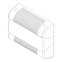
d) Air suction unit: this serves to suck the air from the
outside and inject it into the combustion chamber
with the consequent expulsion of the flue gases
outwards through the appropriate flue gas duct.
SUCTION UNIT MOTOR RATING PLATE DATA
Electrical power supply . . . . . . . . . . . . . . . . . . . . . . . . . . . . . . . . . . . . . . . . . .230 VAC 50 Hz
Insulation . . . . . . . . . . . . . . . . . . . . . . . . . . . . . . . . . . . . . . . . . . . . . . . . . . . . .CLASS H
Motor pack . . . . . . . . . . . . . . . . . . . . . . . . . . . . . . . . . . . . . . . . . . . . . . . . . . . .da 30 mm
Power . . . . . . . . . . . . . . . . . . . . . . . . . . . . . . . . . . . . . . . . . . . . . . . . . . . . . . . .20 WATT