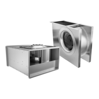
DVS fans DVSI fans DHS fans 1–phase 230 V
DVS 400 E6 DVSI 400 E6 DHS 400 E6
DVS 500 E4 DVSI 500 E4
DVS 500 E6 DVSI 500 E6
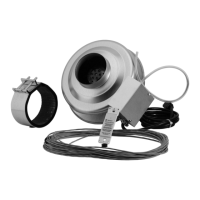
DVS fans DVSI fans DHS fans 3–phase 400 V
DVS 311 DV DVSI 311 DV DHS 311 DV
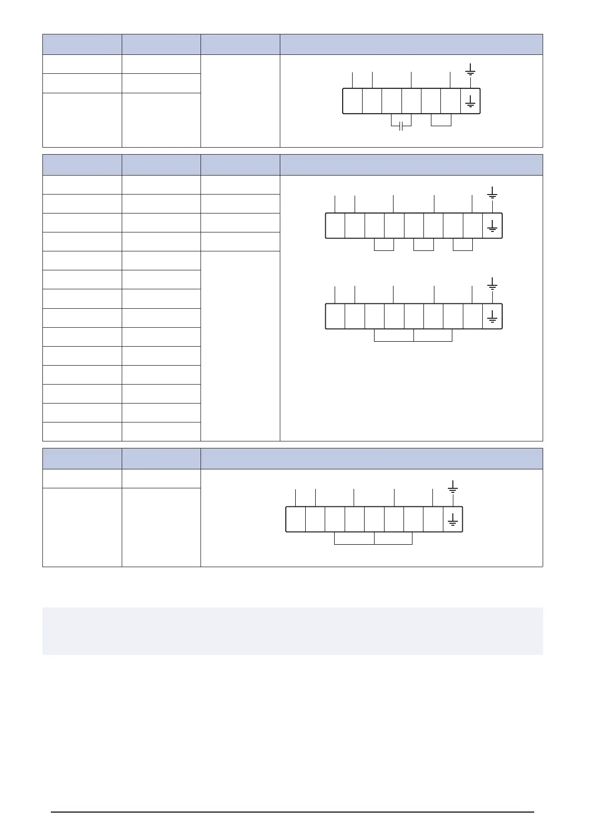
TK
TK L1 L2 L3
TK TK W2 U1 U2 V1 V2 W1
Delta connection
TK
TK L1 L2 L3
TK TK W2 U1 U2 V1 V2 W1
Star connection
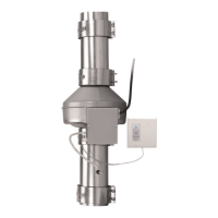
DVS 355 DV DVSI 355 DV DHS 400 DS
DVS 400 DS DVSI 400 DS DHS 400 DV
DVS 400 DV DVSI 400 DV DHS 450 DV
DVS 450 DV DVSI 450 DZ DHS 500 DS
DVS 500 D4 SA DVSI 500 D4 SA
DVS 500 DS DVSI 500 DS
DVS 500 DV DVSI 500 DV
DVS 560 DS DVSI 560 DS
DVS 560 DV DVSI 560 DV
DVS 630 DS DVSI 630 DS
DVS 630 DV DVSI 630 DV
DVS 710 DS DVSI 710 DS
DVS 710 DV DVSI 710 DV
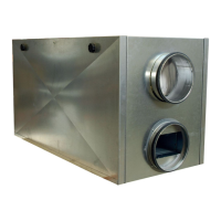
DVS fans DVSI fans 3–phase 380 V
DVS 400 D4 DVSI 400 D4
TK
TK L1 L2 L3
TK TK W2 U1 U2 V1 V2 W1
Star connection
DVS 450 D4 DVSI 450 D4
12.3.3 Wiring diagrams for DVN fans and DVNI fans EC
Note:
The wiring diagrams show connection possibilities for different speed control options. The available speed control options are
explained in the list that follows each wiring diagram.
27