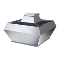
DVC-S fans DVCI-S 3–phase 380–480 V
DVC 450D–S EC DVCI 450D–S EC
BK
L2
BK
L1 L3
L2L1 L3 NC
COM
RSB
RSA GND
0-10V +10V
BK
W
H
WH
BN
WH
BU
YE
RD
10
0
10K
0-10V
-
-
+
+
YE/GN
A
B
C
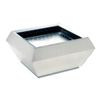
DVC 500D–S EC DVCI 500D–S EC
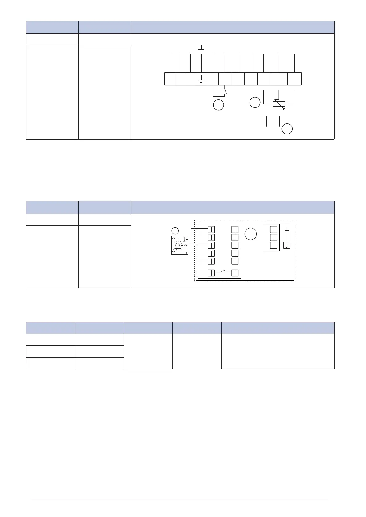
A. Error signal relay/alarm
B. 0-10 V potentiometer, pre-wired:
– 10 V > n = maximum
– 1 V > n = minimum
– <1 V > “n = fan stops
C. Optional external 0-10 V speed control
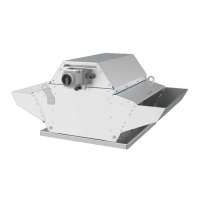
DVC-S fans DVCI-S 3–phase 400 V
DVC 560D–S EC DVCI 560D–S EC
GND
IO1
IO2
IO3
Vout
GND
RSA
L1
L2
RSB
L3
RSA
RSB
NC COM
A
LED
DVC 630D–S EC DVCI 630D–S EC
A. Terminal box with connected potentiometer
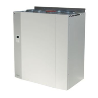
12.3.5 Wiring diagrams for fans with pressure controller
DVC-P fans DVCI-P fans DVC-POC fans DVCI-POC fans
DVC D-P DVCI D-P DVC-POC DVCI-POC Refer to the separate instruction manual for
wiring diagrams and controller instructions
that are included in the delivery of fans that
are delivered with a pressure controller.
DVC E-PK DVCI E-PK
DVC E-P DVCI E-P
Pressure controller overview
33