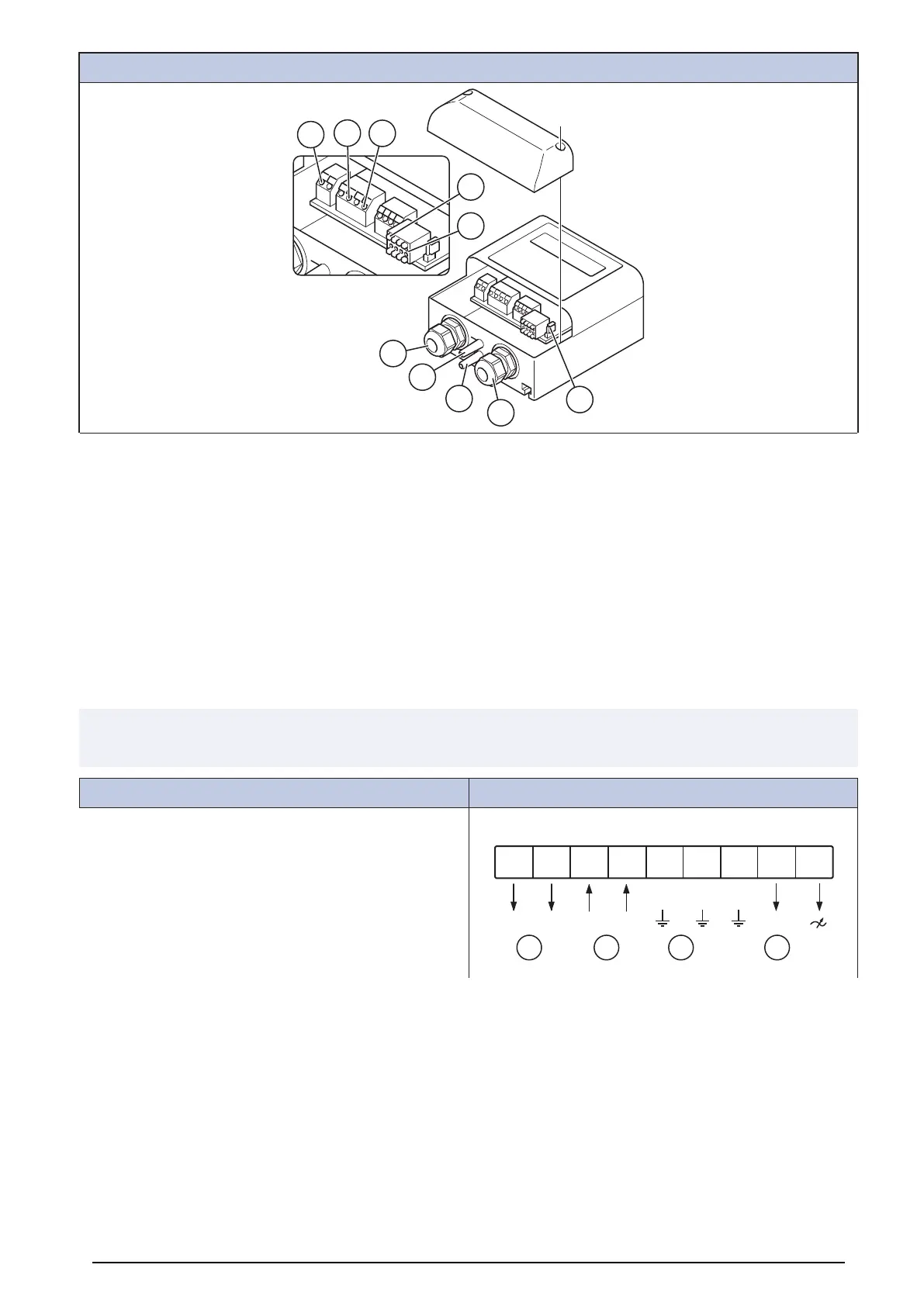
Pressure controller PCA–2 1000
1. Signal relay (terminals: 13, 14)
2. Supply voltage (terminals: U
S
, GND)
3. Output signal 0...10 V (terminals: A, GND)
4. Cable gland M16
5. “Minus” — connection in areas with lower pressure
6. “Plus” + connection in areas with higher pressure
7. Digital input D1 (terminals: 1, 2)
8. Input outdoor temperature sensor (terminals: TF, TF)
9. MODBUS interface (terminals: GND, A, B, ID1, ID2 and jumper J1)
12.3.6 Wiring diagrams for speed controller for AC motors
Note:
The selection of electrical accessories must be done in line with the technical parameters of the product.
RE
Manual 5-step transformer.
RE 1,5
N N N
RE 3 RE 5 RE 7
~ ~
DCBA
A. Relay connection. There is always 230 V between ~ and N when the transformer knob is in one of the positions 1–5.
B. Mains supply
C. Earth
D. Fan
34