4.2.5 To set up the controller for
CAV/VAV
The fan is delivered with an EC motor and an air flow control-
ler device which is factory set for maximum airflow in CAV
(constant air volume control) mode. The CAV controller
measures the air volume and adjusts the 0-10 V output signal
for the EC motor to keep the air volume constant.
To set up the controller for CAV
1 Press “Down” to go to “Base set-up”.
2 Press “P” to enter the menu.
3 Press “Down” to go to “Mode” and press “P” to choose
5.01 CAV control.
4 Press “Down” to go to “Metric units” and press “P” to
choose “1: metric unit” (The factory setting, measures in
Pa, m3/h, K-factor).
5 Press “Down” to go to “Measuring range” and press “P”
to set the measuring range:
• 1 = 0-1000 Pa
• 2 = 0-500 Pa
• 3 = 0-300 Pa
• 4 = 0-200 Pa
6 Press “Down” to go to “K-Factor” and set the K-factor de-
pending on product size. See table below.
Table 1 K-factor
Model K-factor
MUB-CAV/VAV 025 315 EC 143
MUB-CAV/VAV 025 355 EC 132
MUB-CAV/VAV 042 400 EC 159
MUB-CAV/VAV 042 450 EC 213
MUB-CAV/VAV 042 450 EC-K 223
MUB-CAV/VAV 042 500 EC 266
MUB-CAV/VAV 062 560 EC 302
MUB-CAV/VAV 062 630 EC 411
MUB-CAV/VAV 100 630 EC 456
MUB-CAV/VAV 100 710 EC 550
4.2.6 To install weather protection
If the fan is installed outside, Systemair recommends instal-
ling a Weather Protection Roof (WSD) and a Weather Protec-
tion Grille (WSG). These are available as accessories. Visit
www.systemair.com to locate the correct size for your
product.
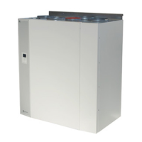
To install the weather protection roof (WSD)
1 Attach the WSD weather protection roof to the frame of
the fan casing with a cap nut with double washers, a dis-
tance bolt and a clinch nut.
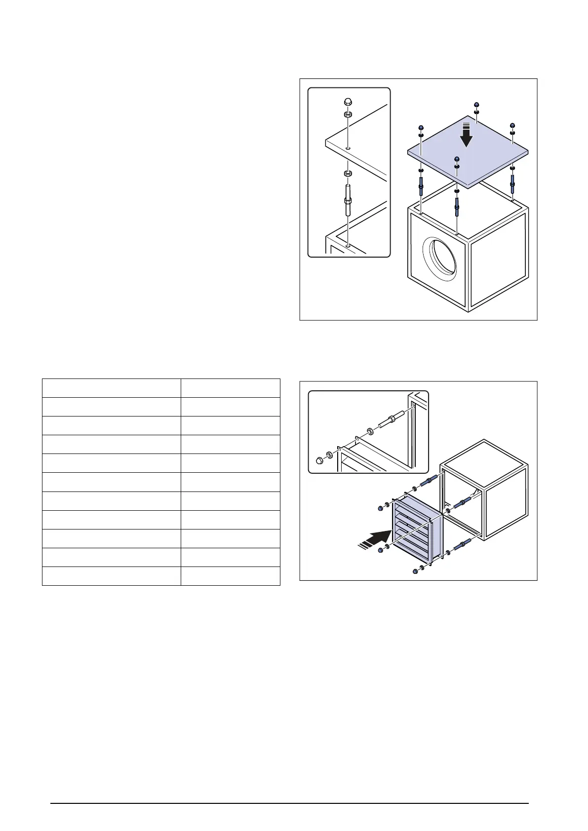
To install the weather protection grille (WSG)
1 Attach the WSG weather protection grille to the frame of
the fan casing with a cap nut with double washers, a dis-
tance bolt and a clinch nut.
9