12.3.3 Wiring diagrams for speed controller for AC motors
Note:
The selection of electrical accessories must be done in line with the technical parameters of the product.
RE
Manual 5-step transformer.
RE 1,5
N N N
RE 3 RE 5 RE 7
~ ~
DCBA
A. Relay connection. There is always 230 V between ~ and N when the transformer knob is in one of the positions 1–5.
B. Mains supply
C. Earth
D. Fan
REE — Thyristor
REE 1 and REE 2 - Surface mounting or with flush mounting
casing included.
REE 4 - Surface mounting.
Note:
Starting currents must be considered when you select the
speed controller type. Products that are used with this
speed controller must have a built-in overheating protec-
tion and must be designed for thyristor speed control.
• L: the connection with cutting function on the speed control.
• (L): the connection without cutting function.
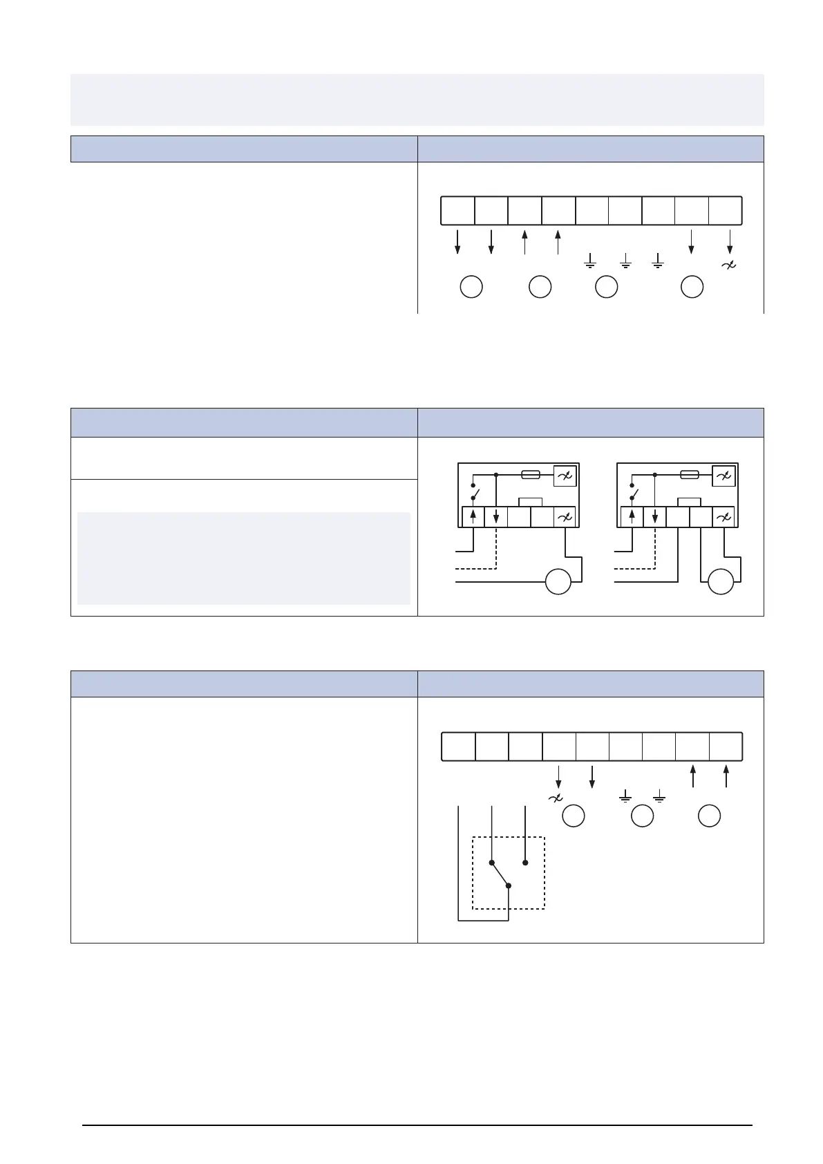
REU
Manual 5-step transformer for high/low speed operation.
Used together with a change-over contact, for example a tim-
er or a thermostat.
REU 1,5
2
1
2 3
3 N N
REU 3 REU 5 REU 7
1 ~
A B C
1. External change-over contact
2. Left selector switch
3. Right selector switch
A. Fan
B. Earth
C. Mains supply
24