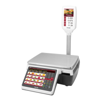
M503 Series chair Scales Service Manual (3.09)
10.4. Check the Load cell
• Remove power from the system, and disconnect the PCB from the Load
cell
• Check the moisture, or foreign material inside.
• Make sure all leads are connected and correctly.
• Check load cell for proper input and output resistances
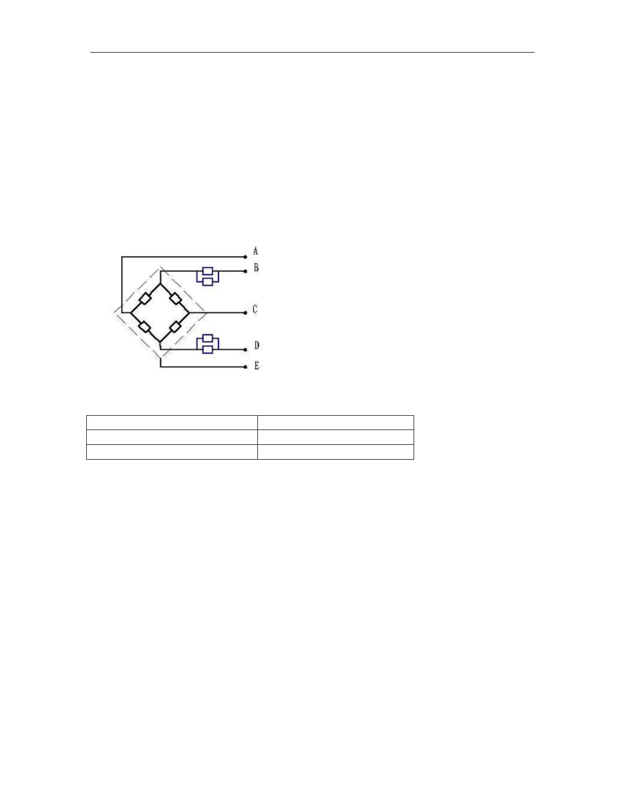
Load Cell Connections
Signal + Green
Supply + Red
Signal - Black
Supply - White
Shield
Red (+ Exc) to White ( –Exc)
Green (+Sig) to Black ( –Sig)
10.5. Check PCB Voltages
If the problem is in the PCB, use a multimeter to check the following voltages
10.5.1 AC Power
Check the AC power socket out put voltage.
• Voltage must be a -20% and +10% of the normal AC voltage.
10.5.2 Adaptor Voltage
Check the adaptor output cable connecter voltage
• Voltage must be minimum 9VDC and maximum 15VDC