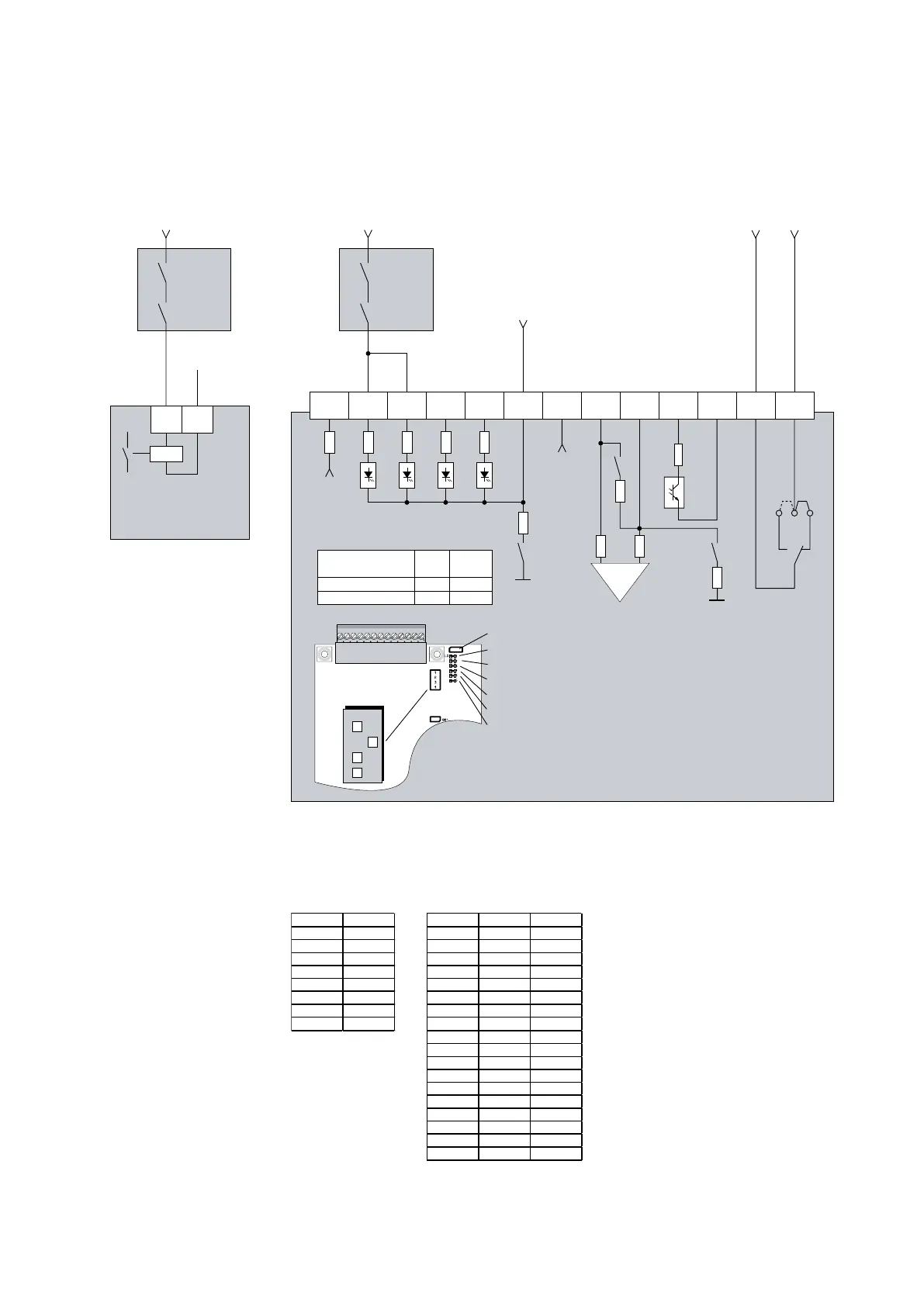
UD-CPU PCB - 0101
Controlboard
for TA-U...
4 5 6 7 8 9 10 11 12 13321
+24V
max 100mA
+10V max 3mA
max 250V/1A
Safety modul
Channal 1+2
Feedback
(STO)
AGND
S1-2
GND
S1-4
10R
S1-1
10R
10R
100R
* At Brake function active (parameter 860.00) is relay output at terminal
12/13 generally configured to control the brake. In this case the terminals
59 and 61 must be used as STO feedback (Analogue-Digital-upgrading)
IN
PTC
OUT
max 50mA
5
4
1
2
3
6 12
9
10
8
11 137
Yellow - input terminal 2
Yellow - input terminal 3
Yellow - input terminal 4
Yellow - input terminal 5
Yellow - output terminal 10/11
Yellow - output terminal 12/13
S1
ONOFF
4
3
2
1
DIP Switch S1
(Factory adjustment)
00 0
1
BR5
BR5 right
right
left
BR5
Safe Torque off
(STO) Channal 2
Safe Torque off
(STO) Channal 1
+24V
0V
Safety modul
+24V
L+
L-
0V
TA-U2...150
max 10mA/Eingang
*
24V DC / 30mA
Supply
Digital inputs
S1-4 DC
External OFF 15-30V
Terminal 1ON
internal
Following configuration of parameters is neccessary for 2 channels operating with feedbac