Multitone Paging Interface Fitting Instruction 17
© Tait Electronics Limited July 2008
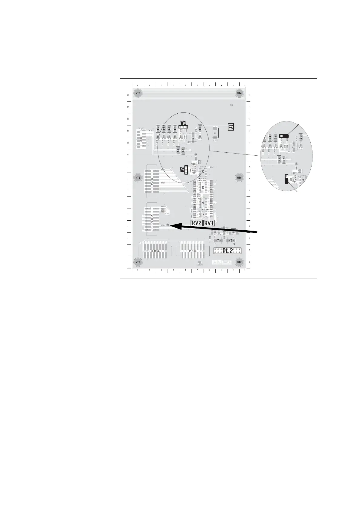
the transmitter using the TX key on the CTU. Adjust RV2 on the
Multitone paging interface for 4.5kHz (WB) deviation.
1.12 Set Fan Voltage
1. On the SI board connect a multimeter between earth and J222.
Adjust RV200 for 1.4V DC (see “Link positions on the SI board” on
page 16).
1.13 User Interface Check
1. Check both Chassis fans are in operation.
2. Check LED operation: Power, TX.
3. Check F1- Toggles back light.
4. Check that F2-F4 LED's on the front panel turn on when the
corresponding function button is pressed.
5. Check CTU digital input and LCD. Use switches 1 and 2 only.
Figure 1.14 Paging Interface Board Test points
3V3 OUTPUT
W2
NON-INV
W1
5V OUTPUT
INVERTED
DATA POLARITY
W2.1
W1.1
J3

 Loading...


