4 Multitone Paging Interface Fitting Instruction
© Tait Electronics Limited July 2008
1.3 Tools and Equipment
Torque-drivers The following torque-drivers are required.
■ Philips #2 bit
■ PZ1 and PZ2 Pozidriv bit
■ Torx T10 bit
Refer to the illustrations in “Disassembly and Reassembly” on page 5 for
the corresponding torque values.
Card Remover Tool To remove the UI board, it is recommended to use the card remover tool
(220-02034-xx) included in the TBA0ST2 tool kit.
Test Equipment The following test equipment is required:
■ test PC
■ calibration and test unit (CTU) (TBA0STU)
■ TB7100 CTU adapter (TBB0STU-TBB, included in TBA0STU)
■ TMAA20-04 cable (RJ12 socket to RJ45 plug, included in TBB0P00)
■ T2000-A19 cable (included in TBB0P00, or TPA-SV-006)
■ RF communications test set (audio bandwidth of at least 10kHz)
■ oscilloscope
■ multimeter
■ function generator
■ DC power supply (capable of 13.8V and 10A for 25W base stations, and
20A for 50W/40W base stations)
The standard test setup is illustrated in the service manual MAS-02731-01-
xx.
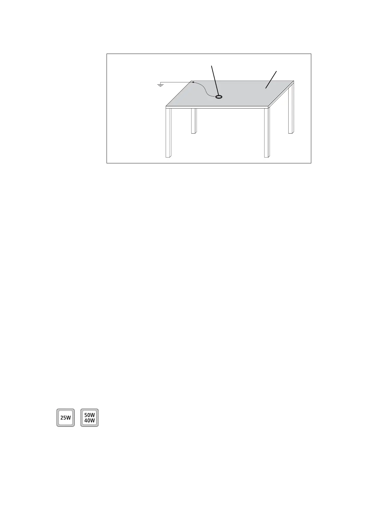
Figure 1.1 Typical antistatic bench set-up
common point ground
(building ground or
mains ground via 1M
ohm series resistor)
conductive wrist strap dissipative rubber
bench mat

 Loading...


