TB9100 Reciter Service Manual Network Circuitry 45
© Tait Electronics Limited January 2006
When PORESET is released the MPC latches the state of the MODCK1
and MODCK2 pins; these provide the initial settings for the clock generator
PLL in accordance with Tabl e 5 . 3.
Pull-up resistors R213 on MODCK1 and R214 on MODCK2 select the
7.5x clock mode so that the CPU clock is initially operated at 7.5 times the
13MHz reference clock (see “Clock Oscillator” on page 81) ie. 97.5MHz.
An optional pull-down resistor, R215, is provided so that the 1:1 clock
mode can be selected if reference clocks higher than approximately 17MHz
are used. There is no provision for selecting the internal MPC crystal
oscillator, which is not used in the ASIF.
Once the PORESET
input is negated and the PLL (see “Clock Generation”
on page 42) has stabilized, the HRESET
and SRESET lines remain asserted
for 512 clock cycles, after which the configuration set-up (see “MPC
Configuration” on page 45) proceeds.
The HRESET
and SRESET lines are bi-directional open-collector, which
allows the MPC to sense a reset signal driven by external open-collector
devices. In the ASIF, this feature is used only for the BDM debug port,
connected to J100 (see “Debug Facilities and Program Loading” on
page 41). Pull-up resistors R201 and R203 ensure correct high logic levels
when no device is asserting HRESET
or SRESET.
MPC Configuration On startup there are several configuration options for the MPC that need to
be set so that it can boot up as well as enable the pins supporting the debug
interface. The MPC obtains these settings by latching the state of the data
bus pins when HRESET
transitions high, but only if the RSTCONF input
pin is taken low. Otherwise, the default configuration setting of all zeroes is
applied.
With RSTCONF
low, the configuration register is still set to its default all-
zeros condition, unless individual data bus line(s) are driven high by external
circuitry, since the MPC enables internal pull-down resistors on its data bus
when HRESET
is asserted. Four tri-state buffers, U200, U205, U210 and
U211, drive selected data bus lines high while HRESET
is active, giving the
configuration settings shown in Tabl e 5 . 4 .
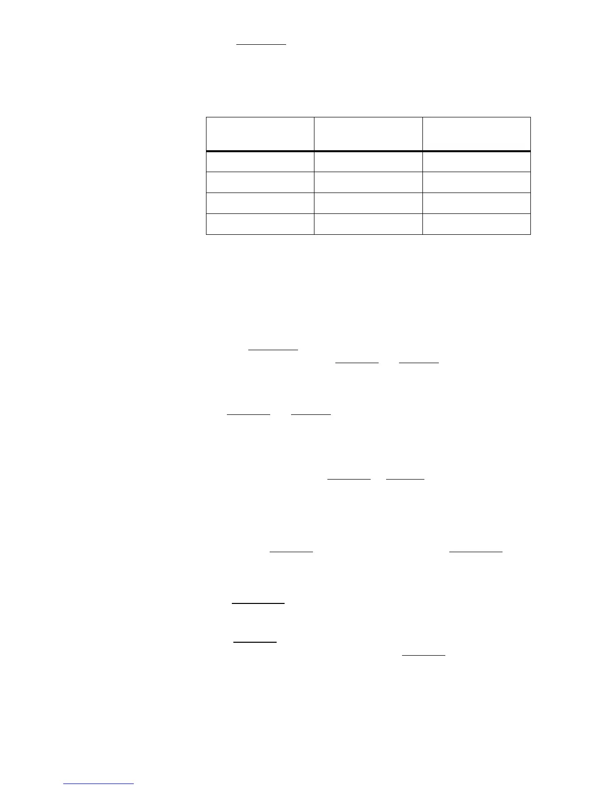
Table 5.3 Power-on Reset PLL Configuration
MODCK[1..2]
Reference clock
source
System frequency
00 Internal crystal oscillator 4 x oscillator clock
01 Internal crystal oscillator 7.5 x oscillator clock
10 External clock source 1:1 mode
11 External clock source 7.5 x external clock

 Loading...


