Radio Installation 51
Installing the power cable
One end of the power cable is connected to the vehicle
battery and the other end plugs into the radio’s
power connector.
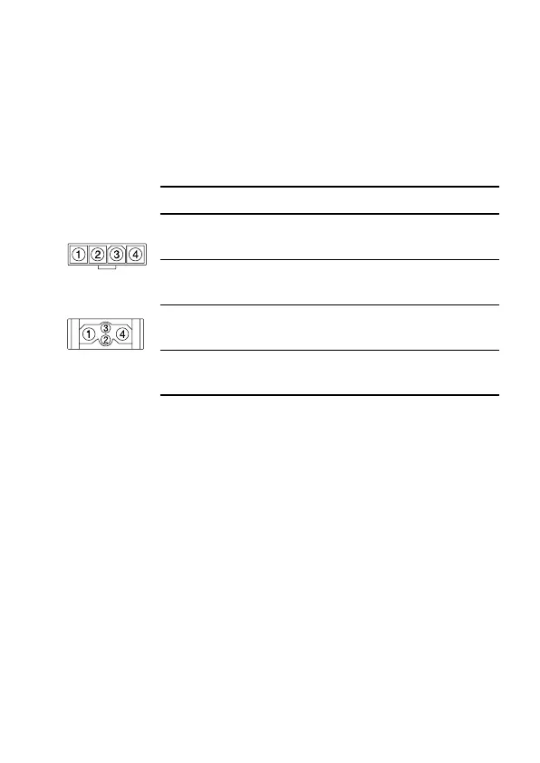
Power connector
The following table explains the pin allocations for the power
connectors on both 25W and 40W/50W radios.
Battery supply voltage
This radio is designed to operate from a nominal 12V negative
ground supply and may draw up to 8A of current (25W radios)
or 15A of current (40W/50W radios). The radio will tolerate a
supply voltage range of 10.8V to 16.0V at the radio.
Caution: In vehicles with a supply voltage greater than
16.0V, such as many trucks, it is essential to
provide a suitably rated DC to DC converter. This
will isolate the radio from excessive battery voltage
and provide the correct DC operating conditions.
Connecting the power cable
Caution: Disconnecting the vehicle’s battery may cause
problems with some electronic equipment, such as
vehicle alarms, engine management systems and
in-car entertainment systems. Check that the
Pin Signal name Description
1 AGND earth return for radio body
power source
2 SPK– external speaker output
3 SPK+ external speaker output
4 13V8_BATT DC power input for radio body
and control head
rear view
25W radio
40W/50W radio
rear view

 Loading...


