- 7 -
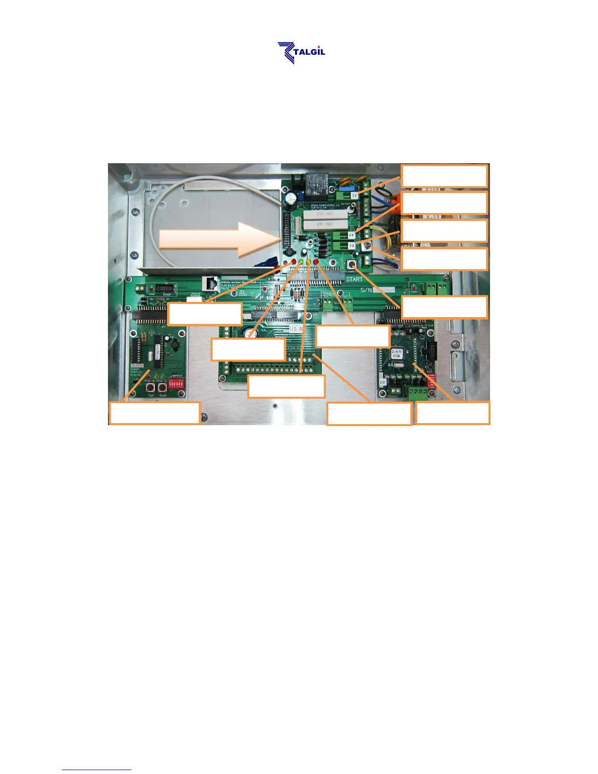
1.3 The Power Supply Board
In the following paragraphs we are going to have a look inside the box of the
DREAM-2 controller, although the information may seem to be a little technical, we
think it can be useful if the user gets familiar with the functions of the switches, the
LEDs, the fuses and some main components of his system.
When the Power Switch is off, only the yellow LED should keep on lighting,
indicating that the charging of the backup battery continues.
When the Power Switch is turned on, some more LEDs of the power supply board
will start lighting.
The red LED indicates that 24v AC arrives to the system from the transformer (in
AC systems only). If this does not happen, the power from the mains and the Main
Power Fuse have to be checked.
As mentioned above, the yellow LED indicates that the charging voltage (13.9v
DC) for the backup battery is generated. If this LED does not light, check the
Charging Fuse. The backup battery should never left to be deeply discharged, it
may harm the battery, therefore if the charging source is expected to be
disconnected for a long period, the backup battery has to be disconnected as well,
otherwise when the charging is restarted, the deeply discharged battery may draw a
high charging current that may blow the Charging Fuse (F3).
The green LED indicates that the 12v DC arrives into the system. The 12v DC is
used for feeding all the electronic boards of the system; it may be generated either
 Loading...