- 49 -
11. System SETUP
The setup process of a DREAM 2 system consists of the following steps:
Step 1 - Network definition – defining the hydraulic network to be
controlled.
Step 2 - Hardware definition – defining the hardware used for the control.
Step 3 - Connections definition – defining where each of the network items are
physically connected.
Those steps are meant to be executed by authorized technicians only. The detailed
explanation about the system setup is out of the scope of this guide and can be
found in the INSTALLATION GUIDE or at the Image Maker of the DREAM2
CONSOLE guide.
11.1 DEALERS DEFINITIONS
The person in charge of the system setup has been given some tools by which he
can do some fine tuning of the system. He can decide to hide unnecessary features
and reveal useful ones. He can dictate some global default parameters, he can
decide about the system behavior in various aspects and he can make changes in the
memory allocation. Because of the sensitivity of the data, changes will be permitted
only after inserting a password (247) and only when the system is idle.
We think that familiarity of the user with the settings made at the Dealers Definitions
may sometimes help him to understand the behavior of his controller, that’s why we
included this information herewith.
◇
1
◇
2
◇
3
◇
4
◇
5
◇
6
◇
7
◇
8
◇
1
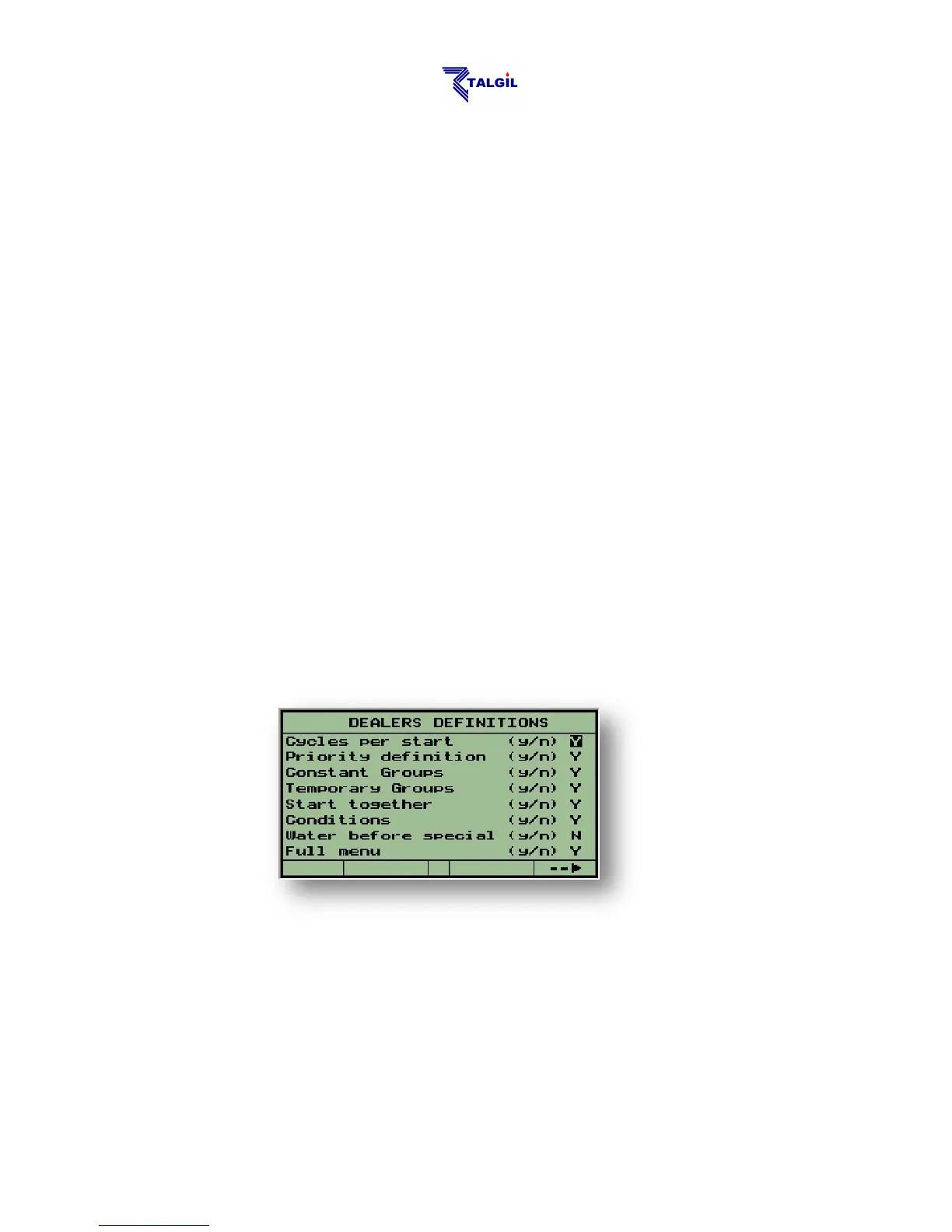
Cycles per start – enable irrigation in cycles, which means repeating the
irrigation several times.
◇
2
Priority definition – enable prioritizing irrigation programs. In case of conflict,
the program with the higher priority will irrigate and the other will wait. Higher
number indicates higher priority.
◇
3
Constant Groups – enable defining groups of valves, G1, G2 etc… The groups
will be remembered and will be usable by various programs. All the valves of the
group will share a common dosage.
◇
4
Temporary Groups – enable grouping valves together by the “&” sign. The
group created this way will have a common dosage and it is recognized only by the
program in which it has been defined.


 To Next Page