- 8 -
from the charging device or from the backup battery, when the charging device is
off. In case of AC systems the charging device is the transformer, while in DC
systems it is the solar panel. The system is protected from excess current
consumption from the 12v DC source, by the 12v DC Fuse (F2).
Important remark: The charging current passes through both the Charging
Fuse and the 12v DC Fuse, so if for some reason the 12v DC fuse is blown there
will be no battery charging, although the charging voltage exists (yellow LED ON).
The red LED of the USB will start lighting only after the Start Button is pushed,
indicating that the system is now up and running. Together with the USB LED of the
power supply board, the red LED on the Mother Board and the three red power
LEDs on the CPU Board █ █ █ will start lighting as well.
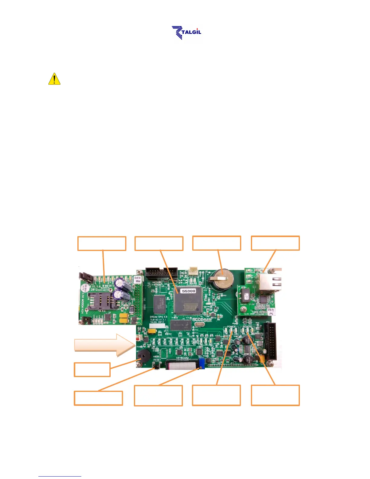
1.4 The CPU board
Looking underneath the front panel, at the back of the LCD display we are going to
find the CPU Board which is the brain behind all the activities of the controller. Let’s
get familiar with some of the components on the CPU board:
 Loading...